
Systems and methods for a turbo low-density parity-check decoder

Active Publication Date: 2007-02-22
QUALCOMM INC
View PDF8 Cites 56 Cited by
  • Summary
  • Abstract
  • Description
  • Claims
  • Application Information

AI Technical Summary

Benefits of technology

[0015] A LDPC decoder comprises a highly structured parity-check matrix that supports variable rates, while still maintaining limited complexity. The LDPC decoder implements resource sharing that reduces the number of parity node processors in a highly efficient manner. The LDPC encoder also comprises an efficient and small memory architecture and reduces interconnect complexity.

Problems solved by technology

While LDPC techniques cannot guaranty perfect transmission, they can be used to make the probability of lost information very small.
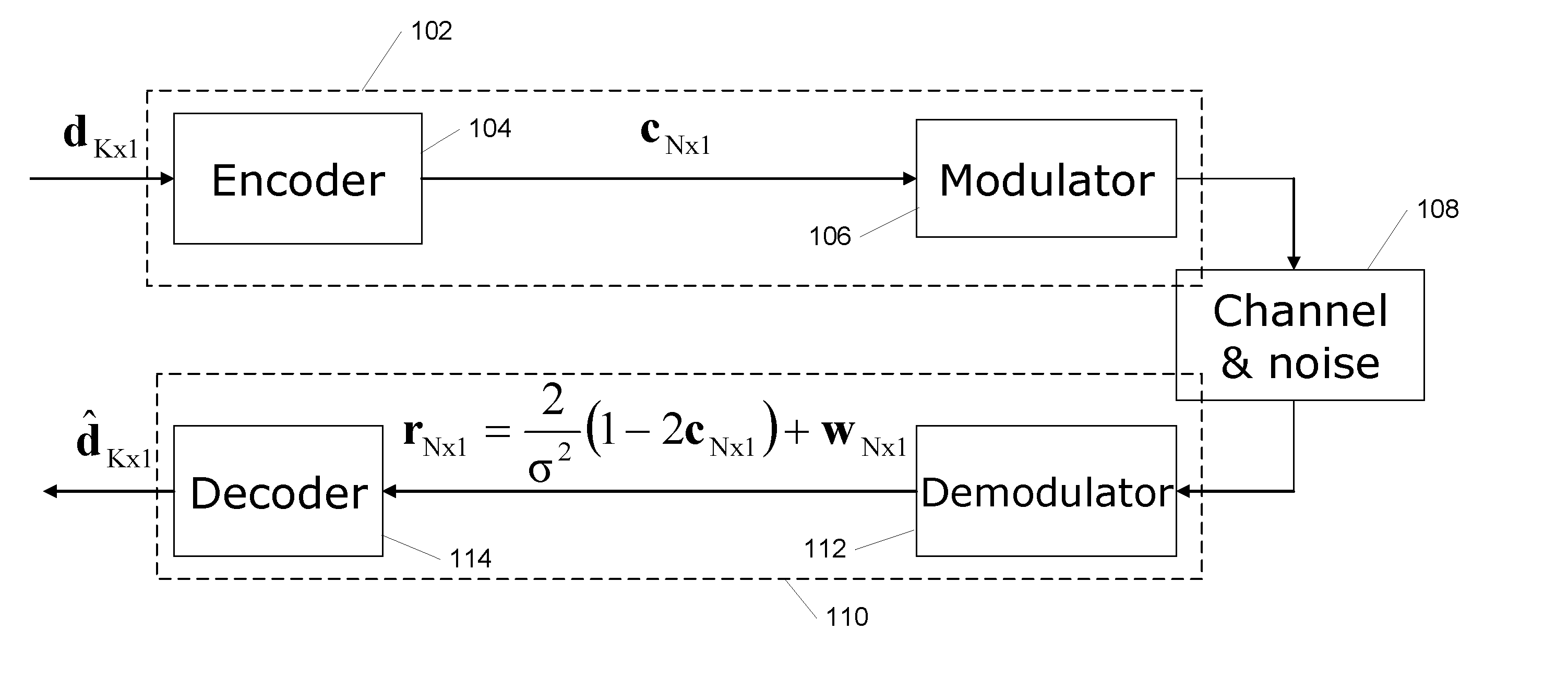
As a result of the noise and channel effects, some of data bits d will be lost in the transmission.
Soft decision decoders are more accurate, but also typically require more resources.
Unfortunately, conventional LDPC decoding techniques result in a high complexity, fully parallel decoder implementations where all the messages to and from all the parity node processors have to be computed at every iteration in the decoding process.
This leads to large complexity, increased research requirements, and increased cost.
Serializing part of the decoder by sharing a number of parity node processors is one option for reducing some of the overhead involved; however, serializing part of the decoder would result in stringent memory requirements to store the messages in an interconnection complexity bottleneck, i.e., complex interconnects between variable node, processors and parity node processors.
Accordingly, serializing part of the decoder is not solely to solve the problems above.
Further, if different data rates are to be supported then the decoder becomes even more complex in terms of memory size, memory architecture, and interconnect complexity.
In general, another problem with conventional LDPC decoders is that the computation performed by the parity node processors are highly complex.
Accordingly, this computations limit the speed of the decoder and increase its size and cost.

Method used


Image

  • Systems and methods for a turbo low-density parity-check decoder
  • Systems and methods for a turbo low-density parity-check decoder
  • Systems and methods for a turbo low-density parity-check decoder

Examples


Embodiment Construction

.”

BRIEF DESCRIPTION OF THE DRAWINGS

[0018] Features, aspects, and embodiments of the inventions are described in conjunction with the attached drawings, in which:

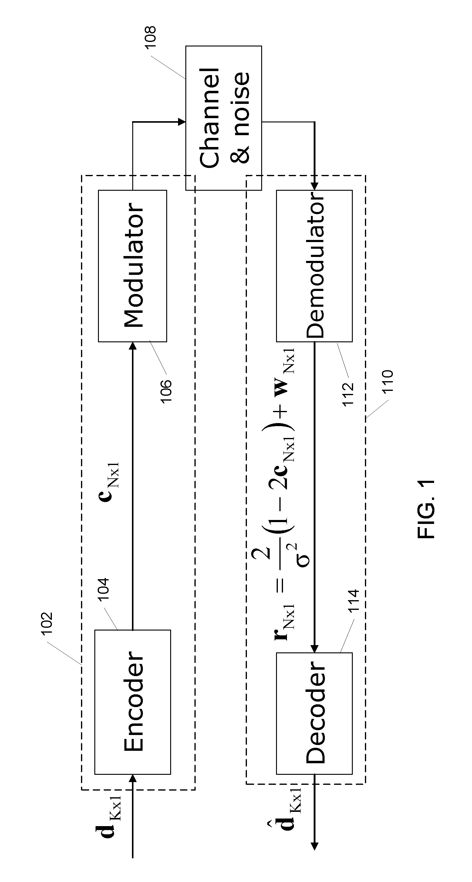
[0019]FIG. 1 is a diagram illustrating an example communication system that uses LDPC codes;

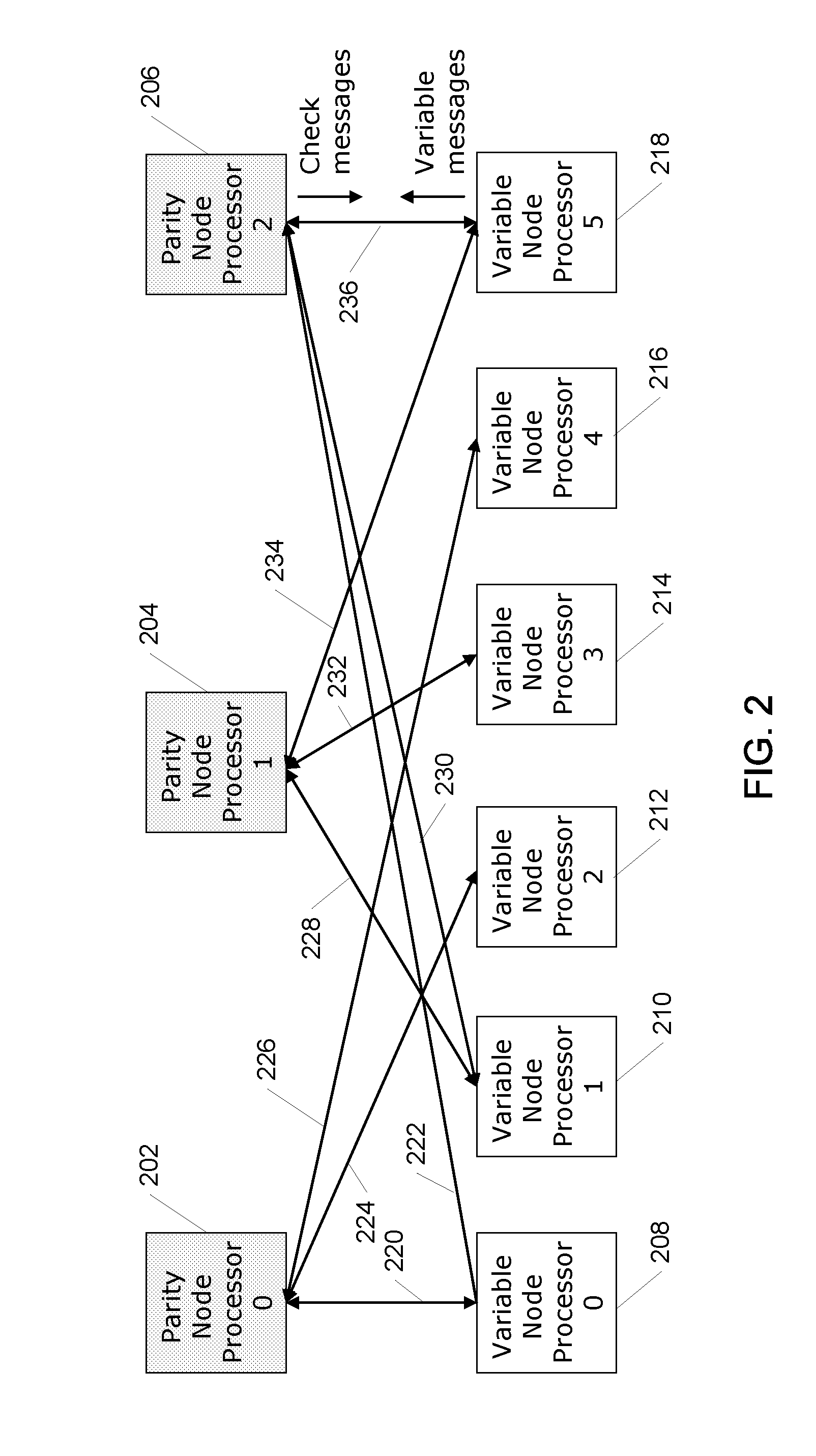
[0020]FIG. 2 is a diagram illustrating the operation of an exemplary parity check matrix;

[0021]FIG. 3 is a illustrating the operation of an exemplary parity node processor;

[0022]FIG. 4 is a diagram illustrating the operation of an exemplary variable node processor;

[0023]FIG. 5 is a diagram illustrating an example exponential matrix configured in accordance with one embodiment;

[0024]FIG. 6 is a diagram illustrating an example parity check matrix in accordance with one embodiment;

[0025]FIG. 7 is a diagram illustrating an example sub-matrix used to construct the parity check matrix of FIG. 6 in accordance with one embodiment;

[0026]FIG. 8 is a diagram illustrating further sub-matrices used to construct the parity check matrix of ...


PUM


Abstract

A method for forming a plurality of parity check matrices for a plurality of data rates for use in a Low-Density Parity-Check (LDPC) decoder, comprises establishing a first companion exponent matrix corresponding to a first parity check matrix for a first data rate, and partitioning the first parity check matrix and the first companion exponent matrix into sub-matrices such that the first parity check matrix is defined using a cyclical shift of an identity matrix.

Description

RELATED APPLICATION INFORMATION [0001] This application claims priority under 35 U.S.C. 119(e) to U.S. Provisional Application Ser. No. 60 / 705,277, entitled “Turbo LDPC,” filed Aug. 3, 2005, which is incorporated herein by reference in its entirety as if set forth in full.BACKGROUND [0002] 1. Field of the Invention [0003] The embodiments described herein are related to methods for Low-Density Parity-Check decoding and more particularly to methods for achieving efficient and cost-effective Low-Density Parity-Check decoders. [0004] 2. Background of the Invention [0005] A Low-Density Parity-Check (LDPC) code is an error correcting code that provides a method for transferring a message over a noisy transmission channel. While LDPC techniques cannot guaranty perfect transmission, they can be used to make the probability of lost information very small. In fact, LDPC codes were the first to allow data transmission rates at close to the theoretical maximum, e.g., the Shannon Limit. LDPC tec...

Claims


Application Information

Patent Timeline
IPC IPC(8): H03M13/00
CPCH03M13/1137H03M13/114H03M13/116H03M13/118H03M13/635H03M13/6516
Inventor LAKKIS, ISMAIL
Owner QUALCOMM INC
Learn More