Method and system for cryogenic cooling

a cryogenic cooling and cooling system technology, applied in the field of cryogenic cooling systems, can solve problems such as the decrease of the cooling time of the system, and achieve the effects of reducing the cooling requirements, reducing the cooling time of the system, and increasing the effective life of the cooling system

Active Publication Date: 2007-03-01
RAYTHEON CO
View PDF14 Cites 8 Cited by
  • Summary
  • Abstract
  • Description
  • Claims
  • Application Information

AI Technical Summary

Benefits of technology

[0006] Certain embodiments of the invention may provide numerous technical advantages. Some, none, or all embodiments of the invention may benefit from the below described advantages. For example, in one embodiment of the invention, a method for cooling inhibits the formation of a convective loop between a cold finger of a cryogenic cooler and a Dewar. Such inhibition of a convective loop results in decreased cool down time for the system. Further, such inhibiting of a convective loop may also increase the effective life time of the cooling system by providing reduced cooling requirements after initial cool down is achieved.

Problems solved by technology

Such inhibition of a convective loop results in decreased cool down time for the system.

Method used


Image

  • Method and system for cryogenic cooling
  • Method and system for cryogenic cooling
  • Method and system for cryogenic cooling

Examples


Embodiment Construction

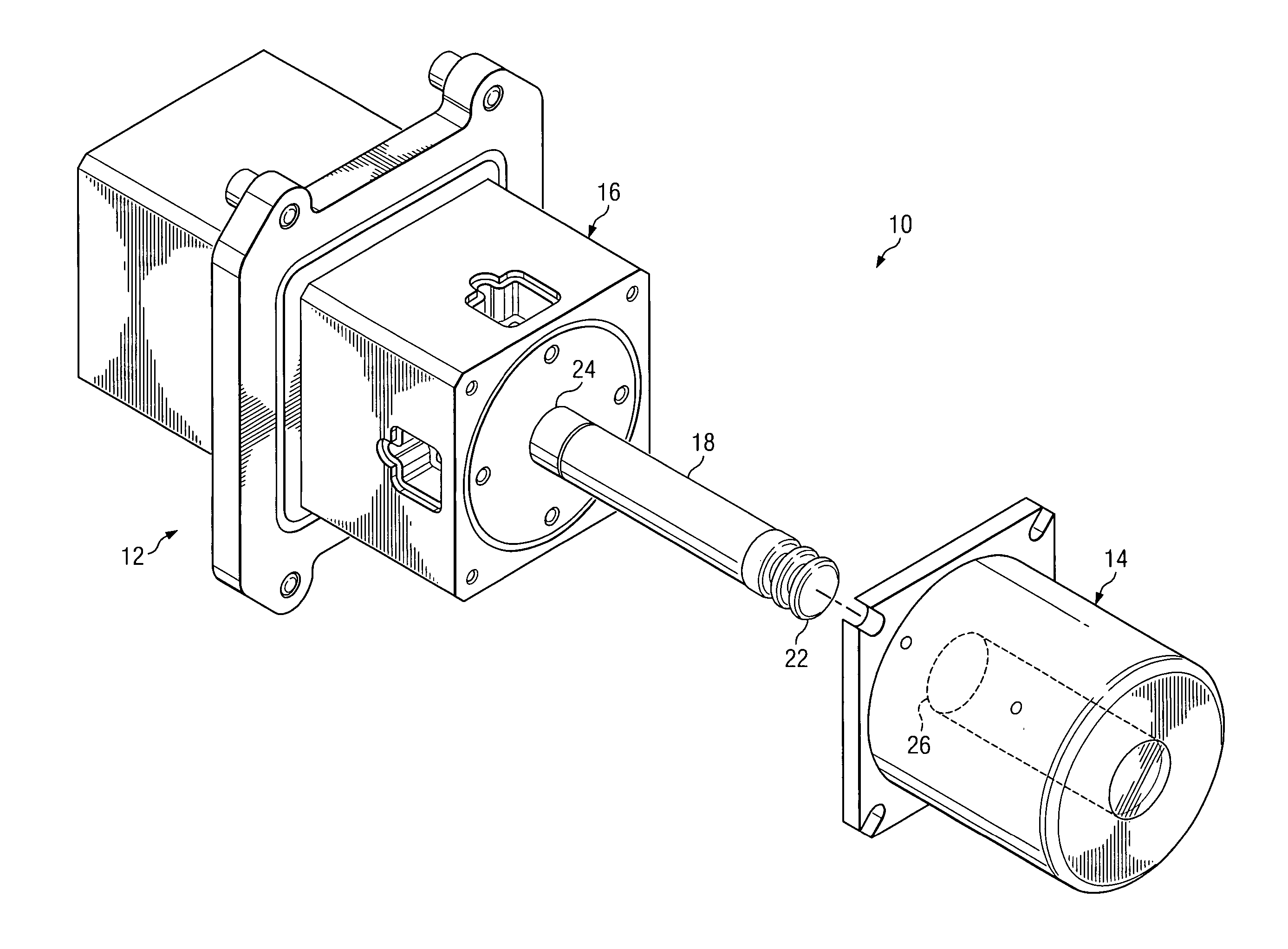
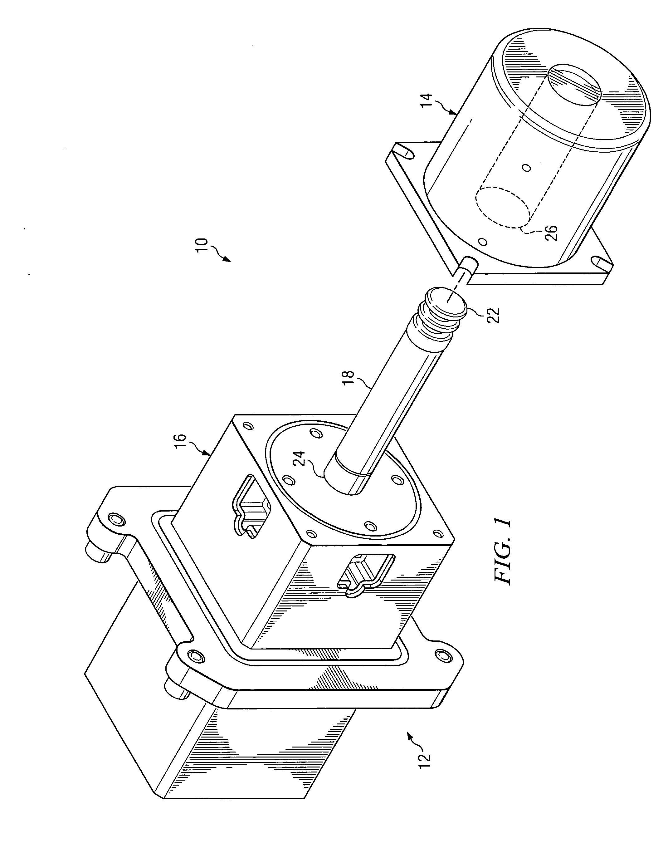
[0012] Embodiments of the present invention and its advantages are best understood by referring to FIGS. 1 through 2A of the drawings, like numerals being used for like and corresponding parts of the various drawings.

[0013]FIG. 1 is a schematic diagram illustrating a conventional cryogenic cooling system 10. Cooling system 10 includes a cryogenic cooler 12 and an associated Dewar 14. Cryogenic cooler 12 includes a cooling section 16 and a cold finger 18. Cooling section 16 generates a cold fluid which is circulated within the interior of cold finger 18. Cold finger 18 is inserted within a void region 26 of Dewar 14 to cool a device, such as an infrared detector formed on part of Dewar 14 (not explicitly shown). Cryogenic cooling systems 10 are well known and are described in the literature, including, for example in U.S. Pat. Nos. 4,028,907; 4,569,203; and 6,070,414.

[0014] An important aspect of the operation of cryogenic cooling systems 10 is the time required to bring detector 2...


PUM


Abstract

According to one embodiment, a method for improving heat transfer between a cold finger of a cryogenic cooler and a Dewar includes forming an annulus between the cold finger of the cryogenic cooler and the Dewar by inserting the cold finger into the Dewar. The cold finger has a first end and a second end. The method also includes inhibiting the formation of convective currents within the annulus in a direction between the first end and the second end. According to another embodiment of the invention, the cooling system includes a cryogenic cooler that includes a cooling section operable to generate cooling fluid and a cold finger operable to receive the cooling fluid. The cooling system also includes a Dewar formed with a void region coupled to an infrared detector. The cold finger is positioned within the void region of the Dewar creating an annulus. The cooling system also includes at least one obstruction disposed within the annulus and operable to inhibit the formation of convective currents in a direction along a length of the cold finger.

Description

TECHNICAL FIELD OF THE INVENTION [0001] This invention relates generally to cooling systems and more particularly to a method and system for cryogenic cooling. BACKGROUND OF THE INVENTION [0002] Cryogenic coolers are often used to remove heat from infrared detectors and associated electronic components in applications where space is limited. The cryogenic cooler is typically inserted into a Dewar (or housing) onto which one or more detector elements are mounted. Some applications often require that an infrared array of detector elements be cooled to liquid nitrogen temperatures, such as 70 degrees Kelvin. Joule-Thomson and Stirling Cycle coolers are the two cooling techniques most often used to provide controlled cooling at such extreme temperatures. [0003] An important consideration in the operation of a cryogenic cooler is the time required to bring the cooled device down to appropriate temperatures such that it may be operated. Another consideration is the power requirements for ...

Claims


Application Information

Patent Timeline
Patent Type & Authority Applications(United States)
IPC IPC(8): F25B19/00F25B9/00
CPCF25D19/00G01J5/061
Inventor WYATT, WILLIAM G.FINNEBURGH, MORRIS E.
Owner RAYTHEON CO
Why Eureka
Try Eureka