Opposed Double Piston Internal Combustion Engine

Inactive Publication Date: 2007-03-01
TSE KWONG WANG
View PDF13 Cites 0 Cited by
  • Summary
  • Abstract
  • Description
  • Claims
  • Application Information

AI Technical Summary

Benefits of technology

[0009] Hence, it is an object of the present invention to provide an improved internal combustion engine or engine topology which overcome or, at least, mitigate disadvantages associated with conventional internal combustion engines. More specifically, it is an object of the present invention to provide an improved internal combustion engine performance by reducing the engine weight-to-power output ratio. It is also an object of the present invention to provide an internal combustion engine or engine topology in which each piston alternatively only needs to go through a single up and down reciprocal motion in order to complete the fuel intake, compression, explosion and exhaust cycles of an engine operation. It is also an object to provide a returning movement for piston free from axle and related mechanism after such piston has moved away by combustion for power generation. It is also an object to provide an internal combustion engine able to consume two fuels at the same time of engine operation for a chance to select an economical or environmental second fuel. As a minimum, it is at least an object of the present invention to provide the public with a choice of a novel internal combustion engine or engine topology to be described hereinafter. SUMMARY OF THE INVENTION
[0018] Preferably, said internal combustion engine has a choice of engine making for only one piston member, one power transmittal member, one rotary member system with a convention cylinder head instead of second piston system for consideration of a more simple engine making but smaller in power output.

Problems solved by technology

The subsequent timely combustion of the compressed fuel causes an explosion to drive the piston away from the cylinder head.
Because an engine cylinder must withstand the enormous explosive force during the engine operating cycles, internal combustion engines are typically made of steel, wrought iron or other ferrous or non-ferrous metal alloys which are inherently heavy and bulky.
However, two sets of rather complicated piston connecting rods are required and a third piston is responsible for a specific combustion chamber area not served by the other pistons.
Since the engine cycle involving fuel combusting piston is the only power generating part of the cycle, the other piston is non-power generating but power consuming, noting that the piston is usually always connected the an external load.

Method used


Image

  • Opposed Double Piston Internal Combustion Engine
  • Opposed Double Piston Internal Combustion Engine
  • Opposed Double Piston Internal Combustion Engine

Examples


second embodiment

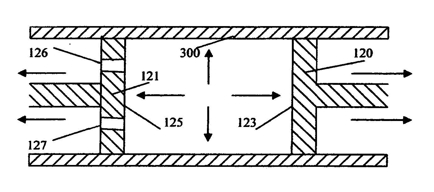
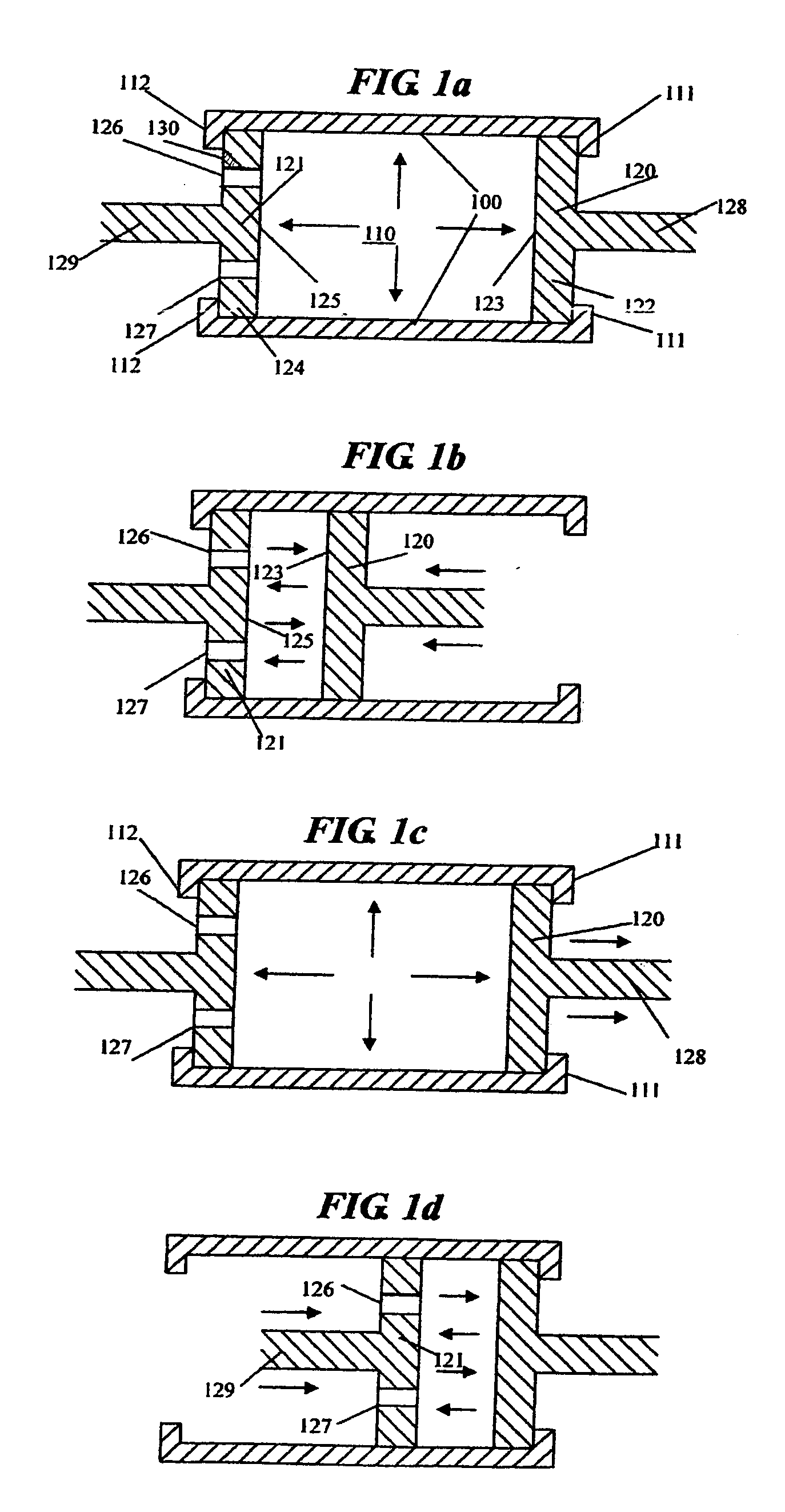
[0039] Referring to FIG. 3a-b, it is another example to avoid damages from direct impacts to the pistons and cylinder and also engine operation. Cylinder (100) has been constructed without any stopping guards and cylinder head to have engine operation different from FIG. 1a-b. An engine combustion of gaseous fuel is taking place in FIG. 3a, and forcing two pistons (120, 121) going away by the power of combustion at the same manner. When two pistons move away and reach a required position for transmission of power, exhaustion outlet (127) is open for exhaustion of emission bringing the pistons loss the power of combustion in FIG. 3a. Outlet (127) is closed immediately after exhaustion finished, and fuel inlet (126) is open for fuel refilling. After refill is completed inlet (126) is closed, compression of fuel starts by two pistons (120, 121) going towards each other at the same time as FIG. 3b. When two pistons compress the fuel in between their combustion faces (123, 125), and reac...

first embodiment

[0041] Referring to FIG. 5, a diagram of sectional view for details of this invention from the cylinder to the axle shows how the power of combustion is transmitted outside from the cylinder to the axle having a free return movement for pistons. Cylinder (100) just has combustion in cavity (110) causing either piston members (120, 121) expelled to their extreme positions against their stopping guards (111, 112) respectively following the process of engine operation as FIG. 1a-d. Two power transmittal arms (128, 129) protruding from the back of the pistons are made in U forms with series of teeth (501, 502) at their ends respectively. These teeth are engaging with the teeth of two revolving cogwheels (503, 504) which are holding main axle (505) for revolving. Either the teeth (501, 502) of the power transmittal arms (128, 129) or the teeth of the cogwheels (503, 504) are made ratchet. For example, two revolving cogwheels are ratchet and are engaging with the solid teeth of the arms. ...


PUM


Abstract

An internal combustion engine including at least one engine cylinder includes a cylinder cavity with first and second stopping members interconnected by a cylinder wall, the cylinder further includes two piston members slidably moveable within said cylinder cavity and between extreme positions intermediate between two stopping members, two piston members combust between their faces and cylinder wall pushing them with their power transmittal members alternatively to revolve the cogwheel and axle. By the ratchet function of power transmittal member or cogwheel, each piston has its free returning movement without clinging with the cogwheel and axle, allowing each piston continuously and alternatively revolves the axle without waste of energy for returning movements. An internal combustion engine having the free return movement by this invention has different choices of engine making in one or two pistons, one fuel or two fuels, stopping members or no stopping members for different engine requirements, substantially increases the usable engine power to enhance efficiency and reduces the weight to power ratio.

Description

FIELD OF THE INVENTION [0001] This invention relates to internal combustion engines and, more particularly, to internal combustion engines in which a common cylinder and two alike pistons are sharing the common combustion chambers for different combustion motions. More specifically, this invention relates to an internal combustion engine of the four-stroke type with two reciprocating piston members which combust within the common combustion chamber to give power by different piston motions alternatively. BACKGROUND OF THE INVENTION [0002] This is a new development different from my previous invention U.S. Pat. No. 6,722,322 by the title “Internal Combustion engine”, and having an important improvement of making the return movement of the piston after combustion is free from engaging with the mechanism of the axle. This improvement makes an internal combustion engine comes more simple and efficient on engine running, and more flexible on design of engine making, wherein my previous i...

Claims


Application Information

Patent Timeline
IPC IPC(8): F02B75/28F01L11/02F02B75/18
CPCF01L3/205F01L11/02F02B75/28F02B75/32
Inventor TSE, KWONG WANG
Owner TSE KWONG WANG
Why Eureka
Try Eureka