
Air intake sound control structure

a technology of air intake and sound control, which is applied in the direction of combustion-air/fuel-air treatment, discharge feed system, instruments, etc., can solve the problems of increasing vehicle exterior noise, generating noise from the intake port, and irritating ears of air intake, so as to reduce the sound pressure of the sound at other than the specific frequency, and maintain the sound pressure at the specific frequency emitted by the resonance of the sound producing body. high

Inactive Publication Date: 2007-03-01
TOYODA GOSEI CO LTD
View PDF15 Cites 43 Cited by
  • Summary
  • Abstract
  • Description
  • Claims
  • Application Information

AI Technical Summary

Benefits of technology

[0012] The present invention has been developed and completed in view of such circumstances. It is therefore an object of the present invention to make it possible to reduce an air intake noise, and at the same time to emit a preferred sound to the vehicle interior.
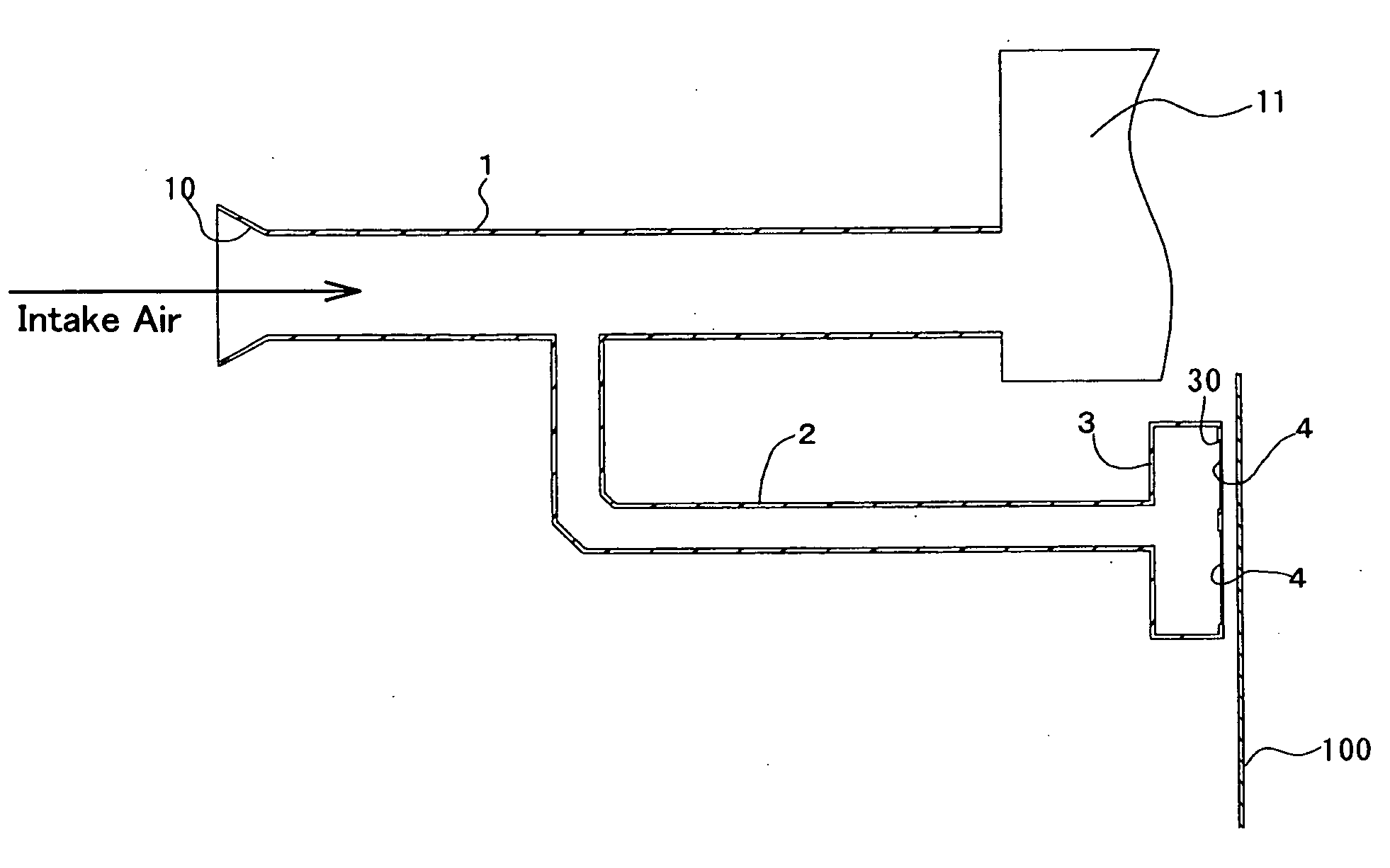
[0019] In the air intake sound control structure according to the present invention, because the sound at the target frequency for suppression in the air intake sound is canceled by the silencing means, the air intake noise from the intake port perceived from the vehicle exterior can be reduced. And, the sound producing body resonates with the sound at the specific frequency in the air intake sound, and accordingly the sound produced by the resonance is emitted from the sound guiding pipe to the outside. Therefore, by disposing the sound producing body adjacent to the vehicle interior, the sound at the specific frequency can be supplied into the vehicle interior, and the air intake sound can be made to be the sound following the accelerator opening degrees. As such, the air intake sound perceived in the vehicle interior can be controlled to be preferable.
[0020] And, because the silencing means exists closer to the side of the air intake flow passage than to the sound producing body, the silencing effect by the silencing means is maintained, even when the natural vibration frequency changes due to the deterioration, etc. of the sound producing body. At least, the reduction effect on the air intake noise perceived in the vehicle exterior can be maintained.
[0022] Here, since the gas in the compartment has lower stiffness than that of the sound producing body, the sound pressure of the sound at other than the specific frequency decreases while being transferred by the gas. This operational advantage is large for the sounds in the low frequency range, so that the sound pressure of booming noises, etc. of low frequencies particularly decreases. Therefore, the sound pressure of the sound at the specific frequency emitted by the resonance of the sound producing body can be maintained to be high, and simultaneously the sound pressure of the sound at other than the specific frequency can be decreased. Accordingly, the air intake noise can be reduced further, and the air intake sound perceived in the vehicle interior can be controlled to be preferable.
[0023] Moreover, since the silencer such as a resonator, etc. can be further formed in the silencing means or the compartment, the sound pressure of the sounds at target frequencies for suppression can be reduced, and the air intake sound perceived in the vehicle interior can be preferable.

Problems solved by technology

In an air intake system of an automobile engine, there arises a problem in that a noise is generated from an intake port when taking air in.
This air intake noise is irritating to ears particularly when the engine runs at low revolution speeds.
However, when the speaker is disposed in the midway of the air intake pipe, the sound of the speaker leaks from the intake port so that the vehicle exterior noise increases.
However, in the sound quality control apparatus described above, even though the sound at the specific frequency corresponding to the natural vibration frequency of the resonant body is amplified, it is difficult to suppress unnecessary sounds out of the air intake sound, and particularly difficult to suppress the emission of the sounds of low frequencies which become booming noises.

Method used


Image

  • Air intake sound control structure
  • Air intake sound control structure
  • Air intake sound control structure

Examples


examples

[0071] Hereinafter, the present invention will be described in detail with reference to examples and comparative examples.

example no.1

Example No. 1

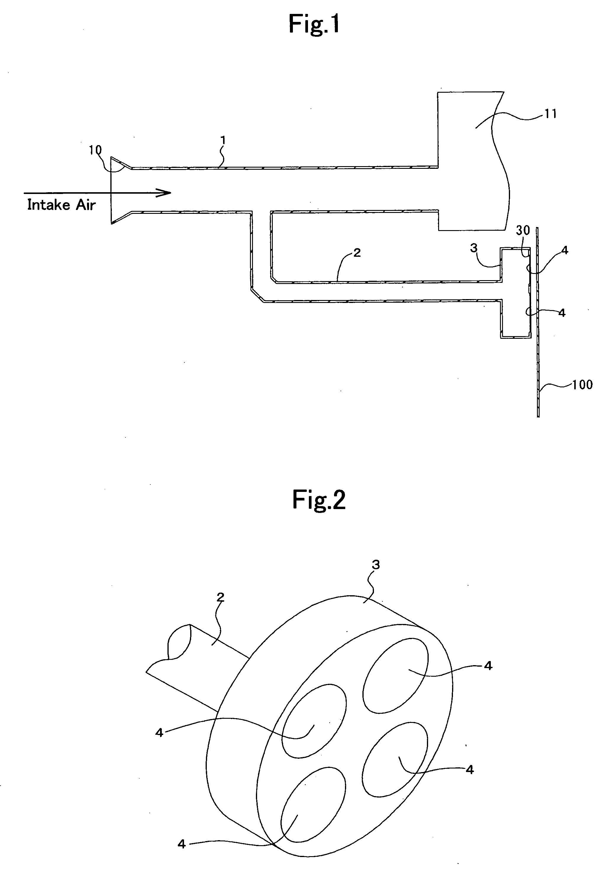
[0072]FIGS. 1 and 2 show an air intake sound control structure according to Example No. 1 of the present invention. A branch duct 2 is branched off between an intake port 10 of an air intake duct 1 and an air filter housing 11, and a cylindrical volume chamber 3 is formed at a distal end of branch duct 2. Four through holes 30 are formed in a bottom portion of the volume chamber 3, and the through holes 30 are covered with sound producing bodies 4 which are formed of resinous plates made of PET and have the thickness of 0.5 mm. And, the bottom portion of the volume chamber 3 faces a dash panel 100 defining a vehicle interior and an engine room with a little space therebetween, and a sound generated by the vibration of the sound producing bodies 4 is transmitted into the vehicle interior by way of the dash panel 100.

[0073] Here, the branch duct 2 and the volume chamber 3 configure a sound guiding duct of the present invention. Moreover, the branch duct 2 and the volume ...

example no.2

Example No. 2

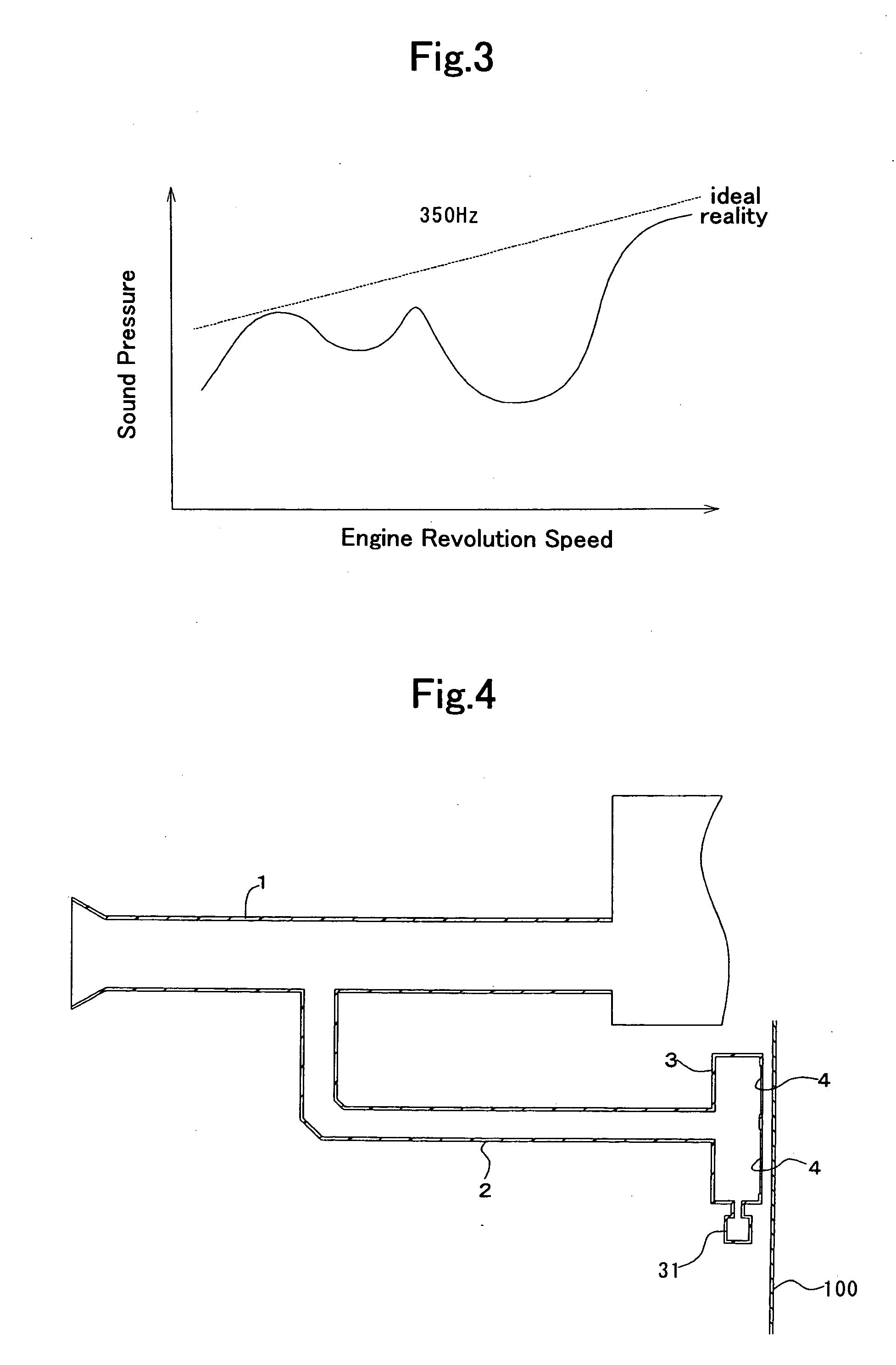
[0077] Except that a Helmholtz resonator-type silencer 31 is formed on a wall surface of a volume chamber 3, an air intake sound control structure according to Example No. 2 of the present invention shown in FIG. 4 is identical with Example No. 1.

[0078] In the air intake sound control structure according to Example No. 2, a portion of an air intake sound which flows into the volume chamber 3 can be canceled by a cavity resonance of the silencer 31. Therefore, out of the air intake which flows into the volume chamber 3, the sound at a natural frequency based on a shape of the silencer 31, that is, the sound at other than a specific frequency which corresponds to a natural vibration frequency of sound producing bodies 4 can be canceled. Since the waveform of the resonant sound in the volume chamber 3 become closer to ideal, it is possible to make the air intake sound transmitted into the vehicle interior preferable.


PUM


Abstract

An air intake sound control structure comprises a sound guiding pipe, a sound producing body, and a silencing means. The sound guiding pipe is branched off from a branch portion formed on a part of an air intake flow passage of an automobile, communicating with the air intake flow passage. The sound producing body is held by the sound guiding pipe at the position spaced apart from the branch portion, thereby sealing the sound guiding pipe, and producing a sound at a frequency which corresponds to its own natural vibration frequency by its vibration. The silencing means is disposed on the side of the branch portion of the sound guiding pipe and canceling a sound at a target frequency for suppression out of the air intake sound. The sound generated by the vibration of the sound producing body is transmitted into a vehicle interior.

Description

BACKGROUND OF THE INVENTION [0001] 1. Field of the Invention [0002] The present invention relates to an air intake sound control structure provided in an air intake flow passage which supplies air to an engine. More particularly, it relates to an air intake sound control structure which reduces an air intake noise, and at the same time can emit a preferred sound in a vehicle interior and exterior. [0003] 2. Description of the Related Art [0004] In an air intake system of an automobile engine, there arises a problem in that a noise is generated from an intake port when taking air in. This air intake noise is irritating to ears particularly when the engine runs at low revolution speeds. Hence, a side branch, a resonator, etc. have been disposed in an air intake pipe conventionally, and sounds at specific frequencies, which are calculated based on the Helmholtz resonance theory, have been reduced. [0005] Moreover, attenuating an air intake sound by producing sounds with a reverse phase...

Claims


Application Information

Patent Timeline
Patent Type & Authority Applications(United States)
IPC IPC(8): F02M35/10
CPCG10K11/22F02M35/1222F02M35/1261F02M35/1294
Inventor SAWATARI, TOMOYUKIHIROSE, YOSHIKAZUOKAWA, SHINTAROINOUE, TOMOKAZUYAMADA, AKIHITO
Owner TOYODA GOSEI CO LTD
Learn More