High flow air filtration system

a high-flow air and filtration system technology, which is applied in the direction of machines/engines, combustion-air/fuel-air treatment, and separation processes, etc., can solve the problems of reducing the output of the engine, the restriction of the path the incoming air must take in order to get to the engine, and the volume of airflow to the engine. to achieve the effect of reducing the velocity of the airflow

Inactive Publication Date: 2007-03-01
ADVANCED FLOW ENG
View PDF13 Cites 18 Cited by
  • Summary
  • Abstract
  • Description
  • Claims
  • Application Information

AI Technical Summary

Benefits of technology

[0014] In a further aspect of the present invention, a method of providing a supply of filtered air to a vehicle engine comprises the steps of passing a supply of airflow from an air inlet duct of the vehicle and into a housing; directing the airflow downward towards a filter element within the housing; reducing the velocity of the airflow; and passing the airflow through the filter element to produce the supply of filtered air.

Problems solved by technology

Although these filtering systems can reduce the contaminants in the air, some filter elements may restrict the air flow into the engine, reducing engine output.
Although filtering systems using these heat shields may provide cooler air, the heat shields reduce the volume of airflow to the engine by restricting the flow into the filter element.
Although these filtration systems may provide a reduction in airflow temperature, the path the incoming air must take in order to get to the engine can be rather restrictive.
In addition, the available filter surface area is limited due to physical geometry of the OEM system.
Likewise, the filter media utilized, while performing its' intended function well, also is very restrictive to air flow.
Others may utilize additional ducting to relocate the filter outside of the engine compartment, however the additional ducting adds restriction to incoming air.
Most of these systems do not have provisions for diverting the incoming air from direct contact with the filter, which in some instances has led to engine stalling.

Method used


Image

  • High flow air filtration system
  • High flow air filtration system
  • High flow air filtration system

Examples


Embodiment Construction

[0034] The following detailed description is of the best currently contemplated modes of carrying out the invention. The description is not to be taken in a limiting sense, but is made merely for the purpose of illustrating the general principles of the invention, since the scope of the invention is best defined by the appended claims.

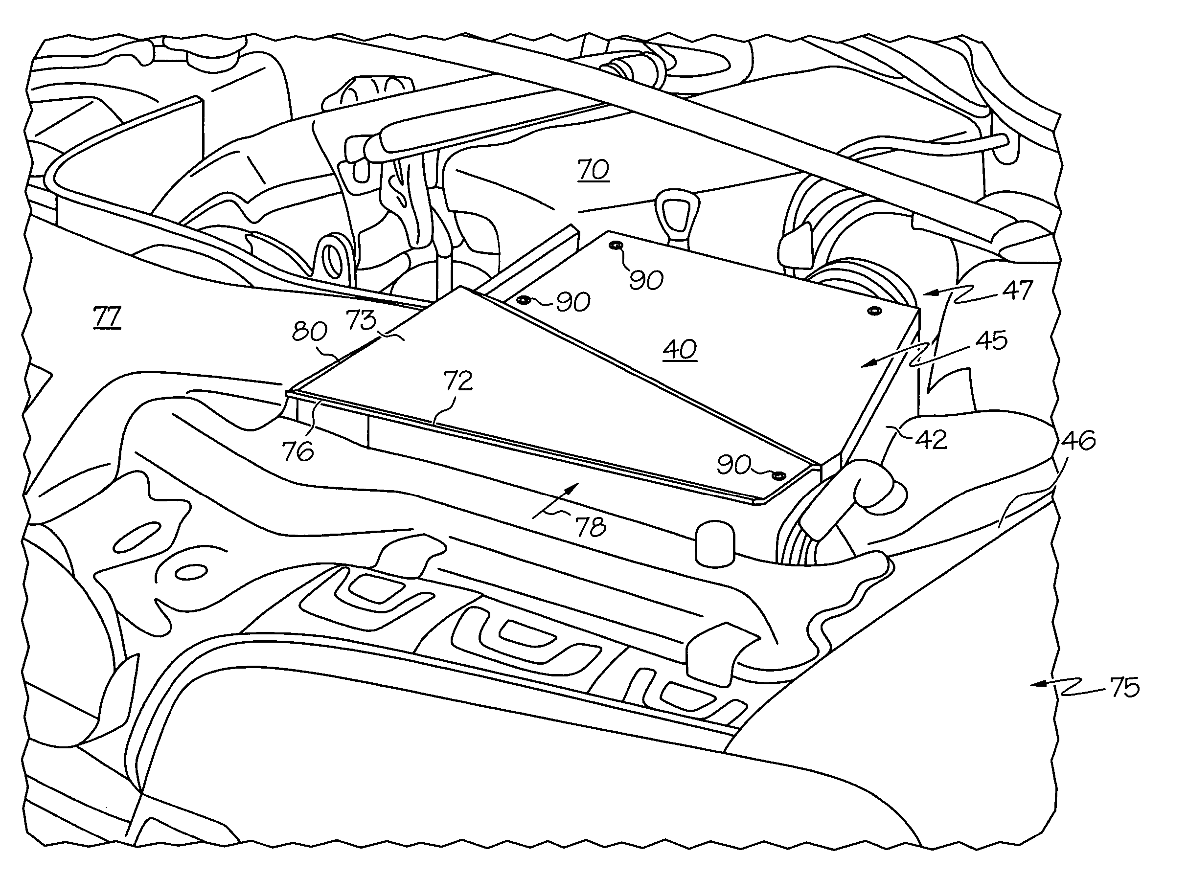
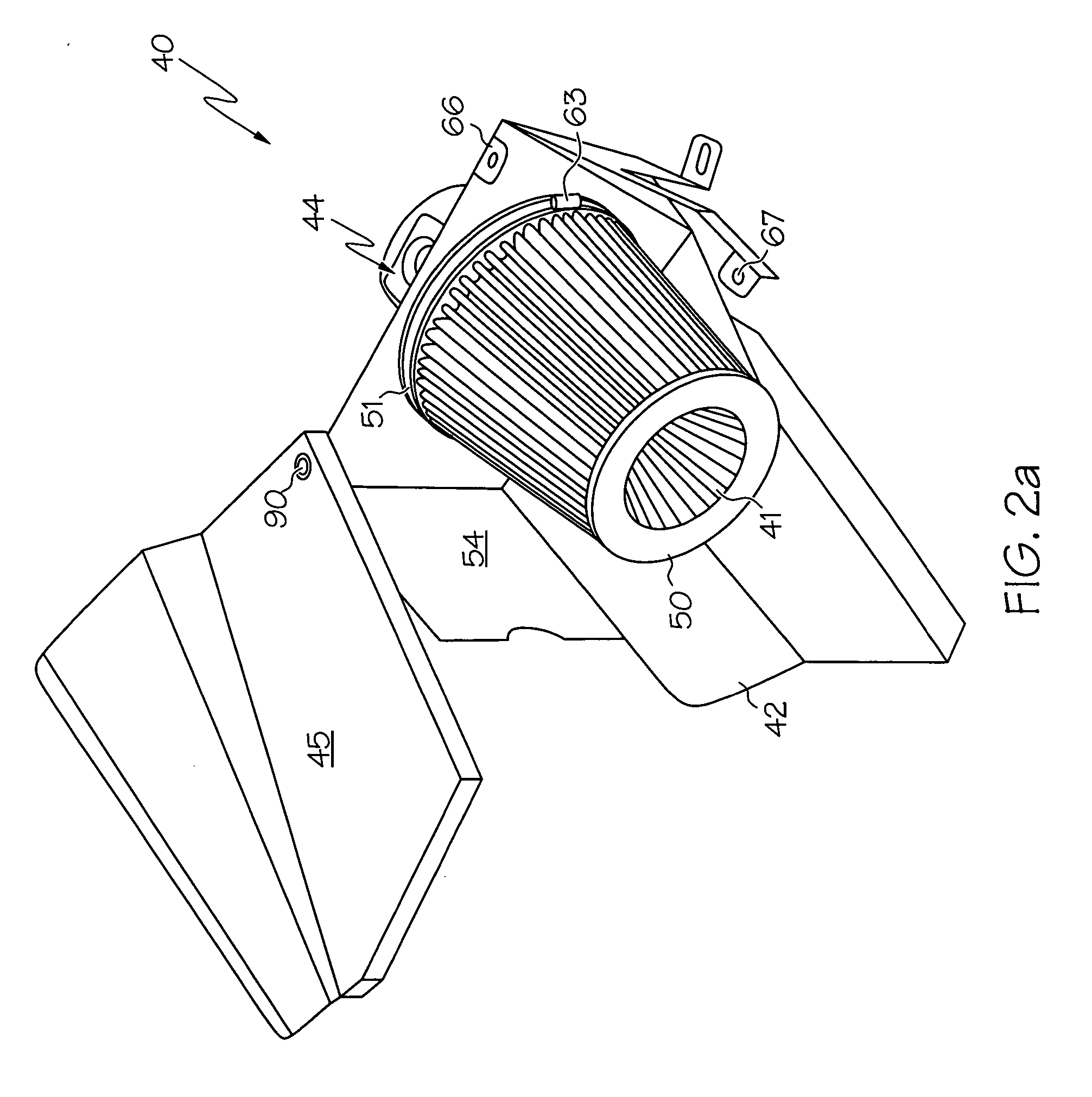
[0035] Broadly, the present invention provides high flow air filtration systems and methods for producing high flow filtered air for vehicles. Embodiments of the present invention may find beneficial use in many industries including automotive, aerospace, and electricity generation. Embodiments of the present invention may be beneficial in applications including automobiles, aircraft and ships. Embodiments of this invention may be useful in any air filtration application.

[0036] In one embodiment, the present invention provides a high flow air filtration system for a vehicle engine. The high flow air filtration system may comprise a filter element wit...


PUM

PropertyMeasurementUnit
distanceaaaaaaaaaa
distanceaaaaaaaaaa
diverter angleaaaaaaaaaa

Abstract

A high flow air filtration system comprises a filter within a housing, a cover removably attached to the housing, an adapter between and in flow communication with the filter and an air intake of an engine. The cover includes a diverter, a flow directing portion, and a lip. The diverter is positioned between the filter and a flow of air from the vehicle ducting. The diverter slows the velocity of the flow and alters its path. The flow directing portion is adapted to direct the flow downward towards the filter. The lip is positioned along the front edge of the cover to increase the volume of external air entering the housing.

Description

BACKGROUND OF THE INVENTION [0001] The present invention generally relates to air filtration systems and, more particularly, to high flow air filtration systems for combustion engines, such as vehicle engines. [0002] Generally, a combustion engine ignites a fuel / air mixture, producing combustion gases, and then extracts energy from these gases. The air provided to the engine is usually filtered to remove dust particles and other environmental contaminants that can damage engine components. [0003] Air filtering systems have included flattened, cylindrical and conical shaped filter elements in flow communication with the air intake of the engine. The filter elements have comprised paper filters, oil bath types, treated filament filters, mesh types, foams and others. Although these filtering systems can reduce the contaminants in the air, some filter elements may restrict the air flow into the engine, reducing engine output. [0004] Engine output may be a function of the volume of air s...

Claims


Application Information

Patent Timeline
Patent Type & Authority Applications(United States)
IPC IPC(8): F02M35/02
CPCB01D46/0002B01D46/0021B01D46/2411B01D46/521B01D2265/05B01D2275/201B01D2279/60F02M35/02483F02M35/10013F02M35/161B01D46/60
Inventor NIAKAN, SHAHRIAR NICKBAJZA, ERIC CHARLES
Owner ADVANCED FLOW ENG
Why Eureka
Try Eureka