Solar energy collector and array of the same

a solar energy collector and solar energy technology, applied in solar heat systems, sustainable buildings, light and heating apparatus, etc., can solve the problems of difficult fabrication of fesnel lenses, difficult wide application, and high cost, and achieve the effect of reducing costs

Inactive Publication Date: 2007-03-01
INST NUCLEAR ENERGY RES ROCAEC
View PDF9 Cites 17 Cited by
  • Summary
  • Abstract
  • Description
  • Claims
  • Application Information

AI Technical Summary

Benefits of technology

[0007] The objective of the present invention is to provide a solar energy collector comprising a plurality of plates assembled in a roof manner and the array of the same, which possesses a lower cost and can collect omni-directional light beams.
[0010] The conventional dome-shaped Fresnel lens is difficult to fabricate, its cost is expensive, and it is difficult for it to have a wide application. On the contrary, the present invention uses a planar plate having protrusion patterns to form a solar energy collector in a roof manner, which possesses a lower cost and can collect omni-directional light beams. Compared to the expensive fabrication of the conventional dome-shaped Fresnel lens, the fabrication cost of the present planar plate is much lower since it is planar. In addition, the present invention assembles the planar plate in a roof manner; therefore the collector can collect omni-directional light beams penetrating therethrough.

Problems solved by technology

The conventional dome-shaped Fresnel lens is difficult to fabricate, its cost is expensive, and it is difficult for it to have a wide application.
Compared to the expensive fabrication of the conventional dome-shaped Fresnel lens, the fabrication cost of the present planar plate is much lower since it is planar.

Method used


Image

  • Solar energy collector and array of the same
  • Solar energy collector and array of the same
  • Solar energy collector and array of the same

Examples


first embodiment

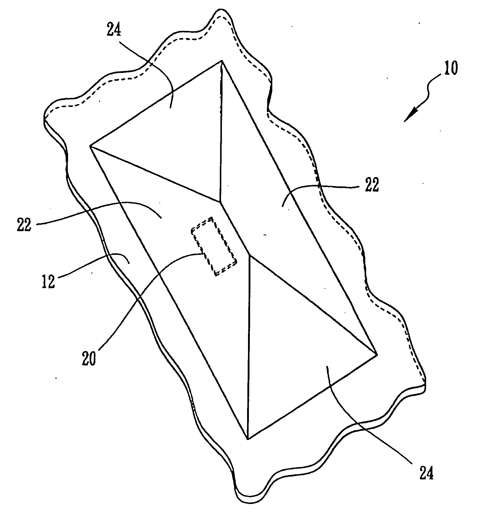
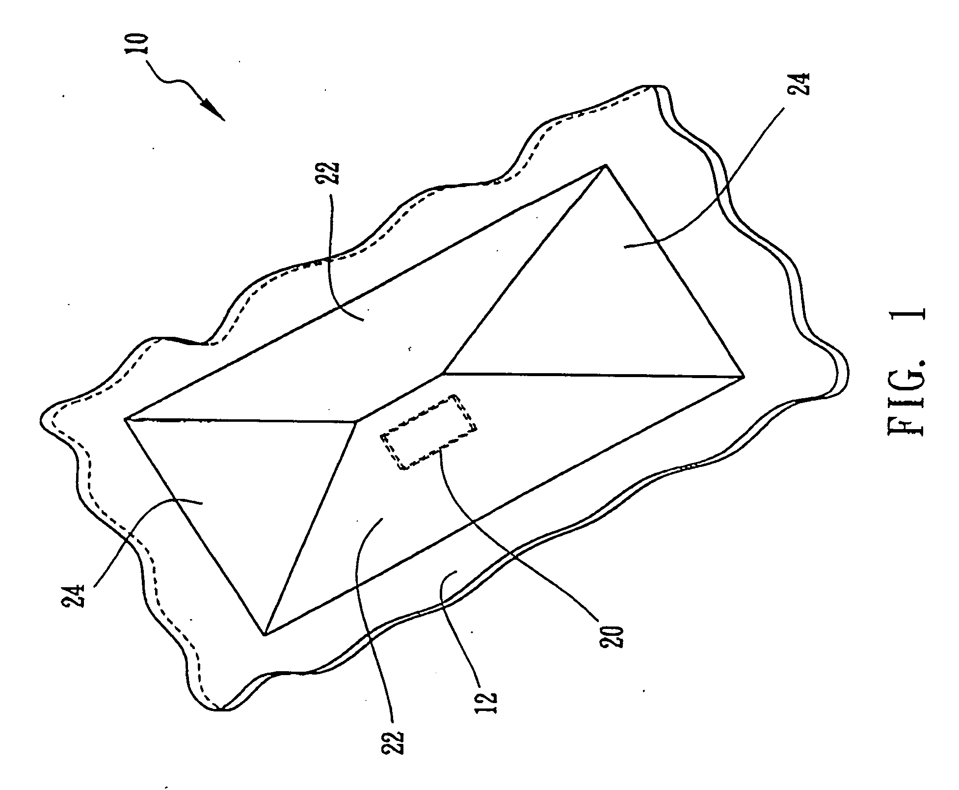
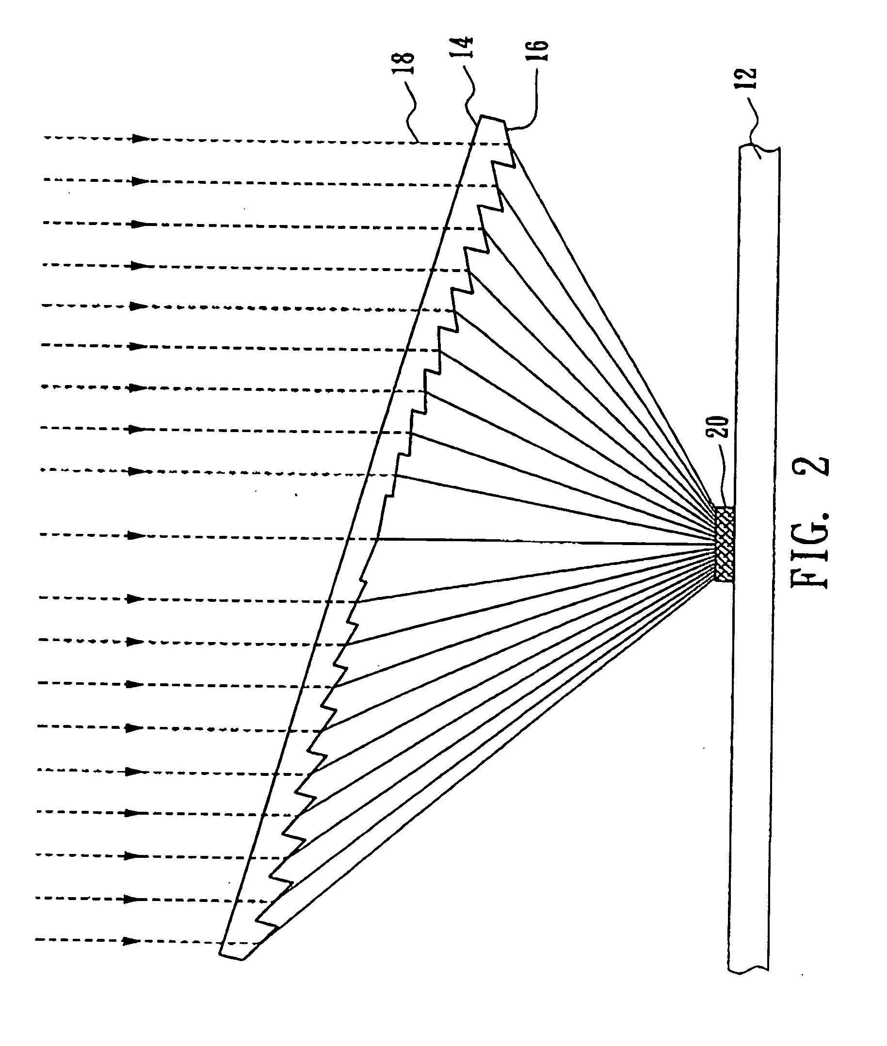
[0018]FIG. 1 and FIG. 2 illustrate a solar energy collector 10 according to the present invention. The solar energy collector 10 comprises a substrate 12, two trapezoid plates 22, and two triangular plates 24 assembled on the substrate as a hip roof. Particularly, the trapezoid plates 22 and the triangular plates 24 are positioned on the substrate 12 in a symmetrically inclined manner, and the assembly of these plates can use fasteners such as bolts and nuts. The trapezoid plates 22 and the triangular plates 24 have a plurality of saw-toothed protrusions 16, i.e., light-collecting patterns, which are capable of refracting light beams 18 that penetrate through the trapezoid plates 22 and the triangular plates 24 to a solar cell 20 positioned on the substrate 12, as shown in FIG. 2. In other words, the protrusion 16 can collect light beams 18 that penetrate through the trapezoid plates 22 and the triangular plates 24 on a solar cell 20 positioned on the substrate 12.

second embodiment

[0019]FIG. 3 illustrates a solar energy collector 30 as a mansard roof according to the present invention. The solar energy collector 30 includes two trapezoid plates 32, two trapezoid plates 34, and one rectangular plate 36 positioned on the substrate 12 in a symmetrically inclined manner. For example, the trapezoid plates 32, 34 may have several supporting beams protruding inward (not shown in the drawings), and the rectangular plate 36 can be positioned on the supporting beams, i.e., the periphery of the rectangular plate 36 can be positioned on the supporting beams on the upper edge of the trapezoid plates 32, 34.

third embodiment

[0020]FIG. 4 illustrates a solar energy collector 40 as a symmetrically hexagonal roof according to the present invention. The solar energy collector 40 includes six first rectangular plates 42 positioned on the substrate 12 in a hexagonal manner, six second rectangular plates 44 positioned on the first rectangular plates 42 in a hexagonal manner and a hexagonal plate 46 positioned on the second rectangular plates 44. Particularly, the first rectangular plates 42 and the second rectangular plates 44 are positioned on the substrate 12 in an inclined manner, and the included angle between the first rectangular plates 42 and the substrate 12 is smaller than the included angle between the second rectangular plates 44 and the substrate 12.


PUM


Abstract

The present solar energy collector includes a substrate and a plurality of plates assembled on the substrate in a roof manner, wherein the plates include a plurality of protrusions capable of collecting a penetrating solar ray on a solar cell positioned at a predetermined region on the substrate. The solar energy collector may include two trapezoid plates and two triangular plates assembled on the substrate in an inclined manner to form a hip-roof. The solar energy collector may include four trapezoid plates positioned on the substrate in an inclined manner and one rectangular plate positioned on the trapezoid plates to form a mansard roof. The solar energy collector may include six first rectangular plates positioned on the substrate in a hexagonal manner, six second rectangular plates positioned on the first rectangular plates, and a hexagonal plate positioned on the second rectangular plates.

Description

RELATED U.S. APPLICATIONS [0001] Not applicable. STATEMENT REGARDING FEDERALLY SPONSORED RESEARCH OR DEVELOPMENT [0002] Not applicable. REFERENCE TO MICROFICHE APPENDIX [0003] Not applicable. FIELD OF THE INVENTION [0004] The present invention relates to a solar energy collector and the array of the same, and more particularly, to a solar energy collector comprising a plurality of planar plates assembled in a roof manner and the array of the same. BACKGROUND OF THE INVENTION [0005] As industry is experiencing rapid growth, petroleum exhaust and the discharge of greenhouse gases from the use of petroleum are getting more and more attention. Nowadays, researchers try to find an alternative energy to petroleum to achieve a stable energy supply. Compared with conventional energy such as coal or nuclear energy, a solar cell uses the photoelectric effect to transform solar energy into electrical energy, which does not generate polluting gases or greenhouse gases such as carbon dioxide, ni...

Claims


Application Information

Patent Timeline
Patent Type & Authority Applications(United States)
IPC IPC(8): H01L31/00F24S23/30
CPCE04D13/033Y02B10/12Y02B10/20Y02E10/40H01L31/0543F24S23/31Y02E10/52Y02B10/10
Inventor CHERN, JYH LONGTZENG, YEN CHANGHONG, HWEN FENCHEN, JAIN CHENGHU, CHIA YUKUO, HUNG ZENSHIN, HWA YUH
Owner INST NUCLEAR ENERGY RES ROCAEC
Why Eureka
Try Eureka