Disc brake pad

a disc brake and disc technology, applied in the direction of braking elements, slack adjusters, braking members, etc., can solve the problems of difficult generalization of the effect of a frequency other than the specific frequency, the countermeasure is not generally applicable, and the resonance cannot be restrained, so as to prevent the brake squeal

Inactive Publication Date: 2007-03-01
AKEBONO BRAKE IND CO LTD
View PDF8 Cites 14 Cited by
  • Summary
  • Abstract
  • Description
  • Claims
  • Application Information

AI Technical Summary

Benefits of technology

[0010] One or more embodiments of the present invention provide a disc brake pad capable of effectively preventing brake squeal by an inexpensive and simple structure by utilizing a viscous member and a weight.

Problems solved by technology

In a general brake, a function of absorbing a vibration frequency of squeal is weak and therefore, the resonance cannot be restrained and the brake squeal is generated.
However, according to the countermeasure against brake squeal utilizing the space portion of the rotor, a type of the brake having the space portion is limited and therefore, the countermeasure is not a generally applicable.
Further, although a restraining effect is achieved for a specific frequency of brake squeal, an effect is difficult to be expected generally for a frequency other than the specific frequency and a further improvement is requested in this respect.
Hence, there is posed a problem to be resolved in view of effectively restraining brake squeal by utilizing a viscous member and a weight.

Method used


Image

  • Disc brake pad
  • Disc brake pad
  • Disc brake pad

Examples


Embodiment Construction

[0036] Exemplary embodiments of the invention will be described with reference to the accompanying drawings.

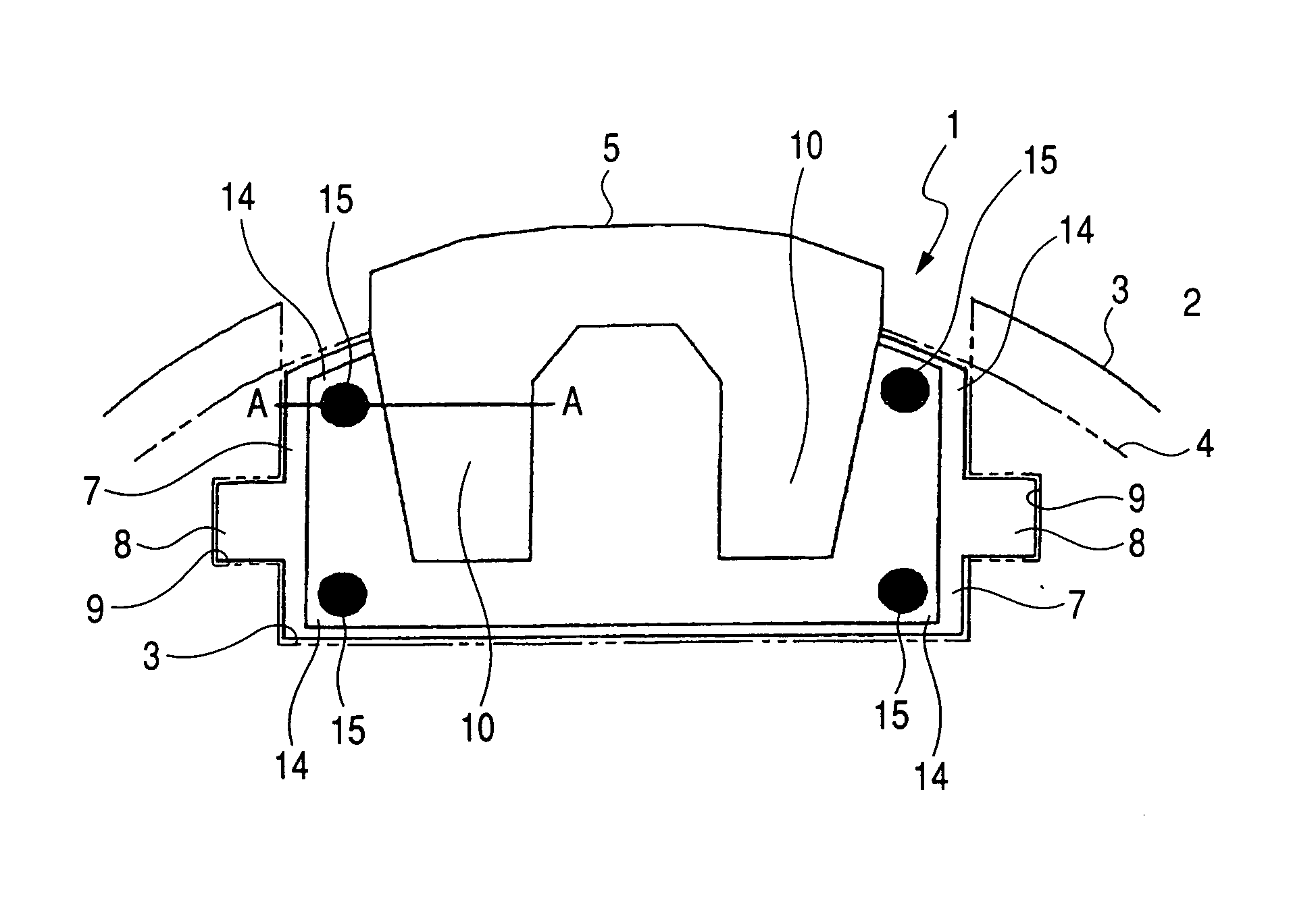
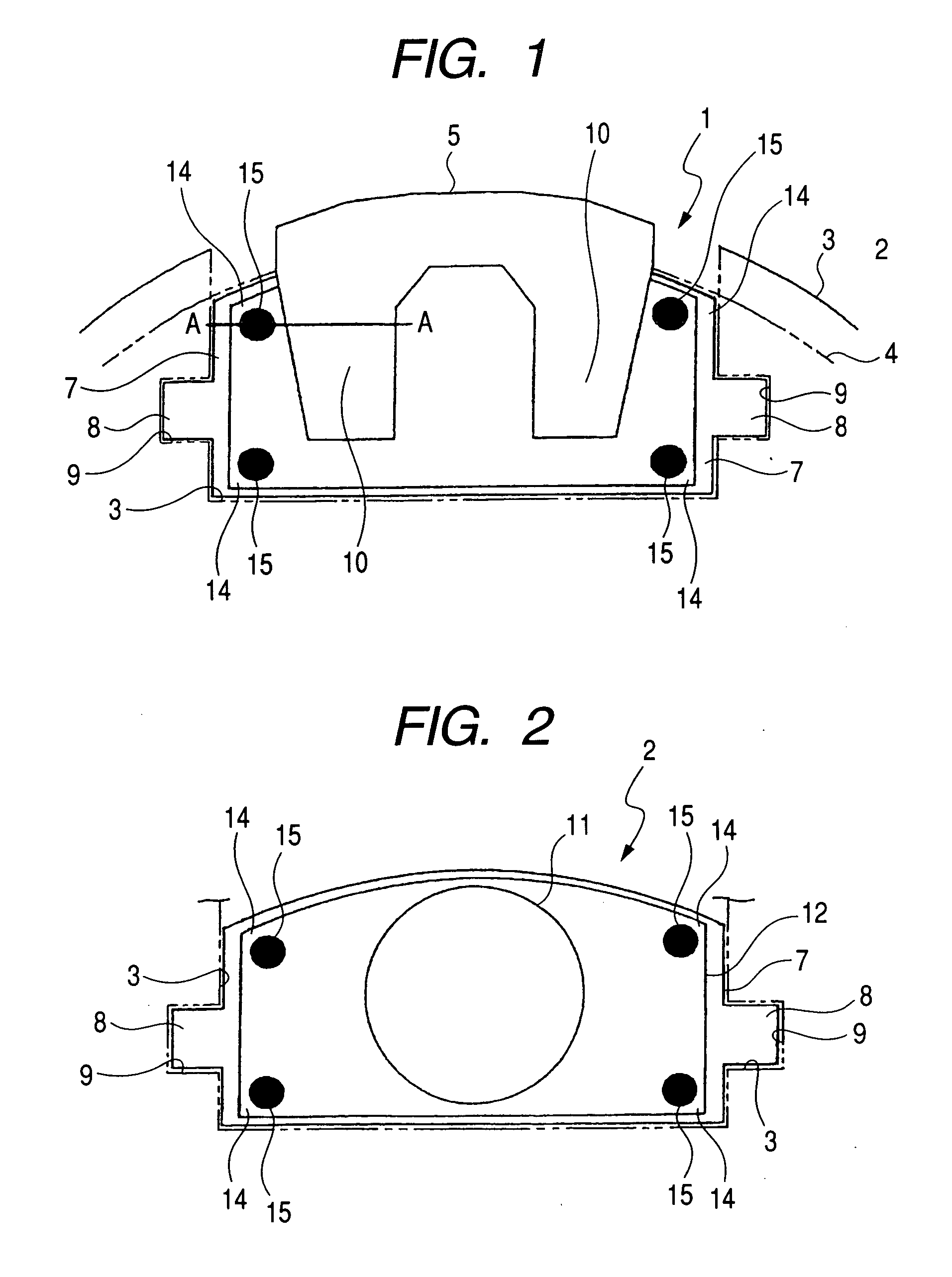
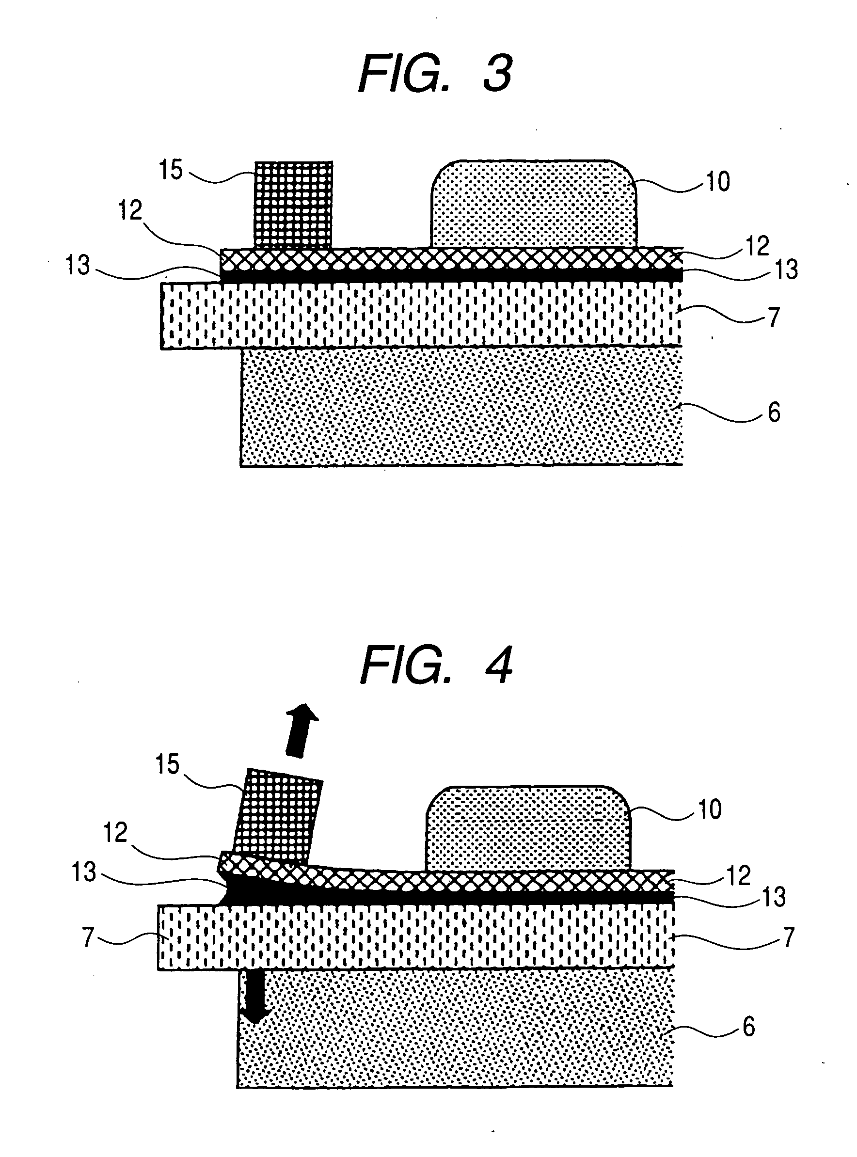
[0037]FIG. 1 is a view showing a state of applying a disc brake pad according to an exemplary embodiment of the invention as an outer pad, FIG. 2 is a view showing a state of applying a disc brake pad according to the exemplary embodiment as an inner pad, FIG. 3 is a sectional view taken along a line A-A of the disc brake pad shown in FIG. 1, FIG. 4 is a sectional view showing a state of operating the disc brake pad shown in FIG. 2.

[0038] A disc brake pad 1 shown in FIG. 1 is a pad arranged on an outer side, and is guided and supported by a fixing member 3 indicated by an imaginary line in directions of moving to and from a rotor 4 similarly indicated by an imaginary line. A caliper 5 including an operating mechanism and guided in directions of moving to and from the rotor 4 relative to the fixing member 3 is arranged to straddle the disc brake pad 1 and the rotor 4. On the ...


PUM


Abstract

At four corners of a pressure plate 7, weights 15 are adhered an adhesive agent for high temperature use. When a frictional vibration is generated by frictionally engaging with a rotor in operating a brake, a shim 12 is displaced relative to a pressure plate 7 by inertia of the weight 14. Grease 13 between the shim 12 and the pressure plate 7 flows so as to produce a viscous resistance to a vibration of the shim 12 relative to the pressure plate 7. By the viscous resistance, the vibration of the pressure plate 7 is attenuated, as a result, brake squeal can be restrained from being brought about.

Description

[0001] This application claims foreign priority from Japanese Patent Application Nos. 2005-251206 filed Aug. 31, 2005, and 2006-163952 filed on Jun. 13, 2006, the entire contents of which are hereby incorporated by reference. BACKGROUND OF THE INVENTION [0002] 1. Field of the Invention [0003] The present invention relates to a disc brake used in a passenger vehicle, a truck, a bus, an industrial machine or the like. [0004] 2. Related Art [0005] In a conventional disc brake for braking a rotating shaft by pressing a brake pad to a rotating rotor, there is a case in which when the pad brakes the rotating rotor or slides relative thereto, owing to a frictional vibration produced by frictionally engaging the rotor and the pad, the rotor or the brake parts are vibrated. When a frequency of the vibration is coincident with a natural frequency of the rotor or the brake parts, the vibration is brought into a resonance state by an eigenvalue coupled vibration. In a general brake, a function ...

Claims


Application Information

Patent Timeline
Patent Type & Authority Applications(United States)
IPC IPC(8): F16D65/38
CPCF16D65/0006F16D65/0018F16D65/092
Inventor NAITO, HISATAKAKOYANAGI, YUKIKAZU
Owner AKEBONO BRAKE IND CO LTD
Why Eureka
Try Eureka