Reel apparatus

a reel and reel technology, applied in the direction of cable arrangement between relatively moving parts, electric cable installation, telephone set construction, etc., can solve the problems of limiting the power supply using the electrical generator, potential safety hazards, troublesome and failure to supply power to the moveable system, etc., to ensure the safety of work on site, increase efficiency, and prevent damage

Inactive Publication Date: 2007-03-01
NUCTECH CO LTD +1
View PDF5 Cites 9 Cited by
  • Summary
  • Abstract
  • Description
  • Claims
  • Application Information

AI Technical Summary

Benefits of technology

[0031] With the reel apparatus according to the embodiments of the present invention, it is not necessary to use the current collector, the sliding contact means, and the cable dragging means, so that the restraints are overcome, thus increasing efficiency.
[0032] Further, the reel apparatus according to the embodiments of the present invention employs a magnetic hysteresis coupling, so that the torque of the motor is converted into a constant torque by the magnetic hysteresis coupling, and then the constant torque is transmitted to the rotatable drum of the reel apparatu...

Problems solved by technology

However, in some situations, supplying power using the electrical generator is restrained by many conditions, so that a commercial power supply has to be used.
However, the conventional commercial power supplying apparatus is r...

Method used


Image

  • Reel apparatus
  • Reel apparatus
  • Reel apparatus

Examples


Embodiment Construction

[0036] Embodiments of the present invention will be described in detail with reference to the accompany drawings, the embodiments described herein are explanatory and illustrative and shall not be construed to limit the present invention.

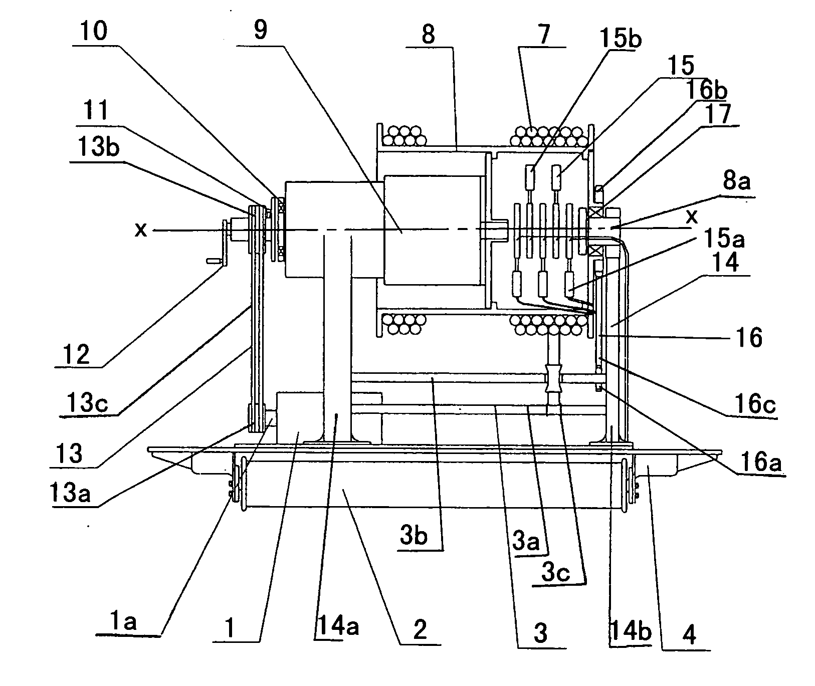
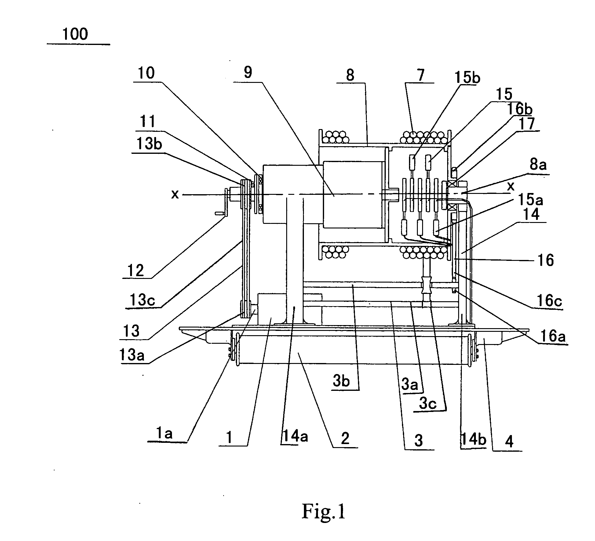
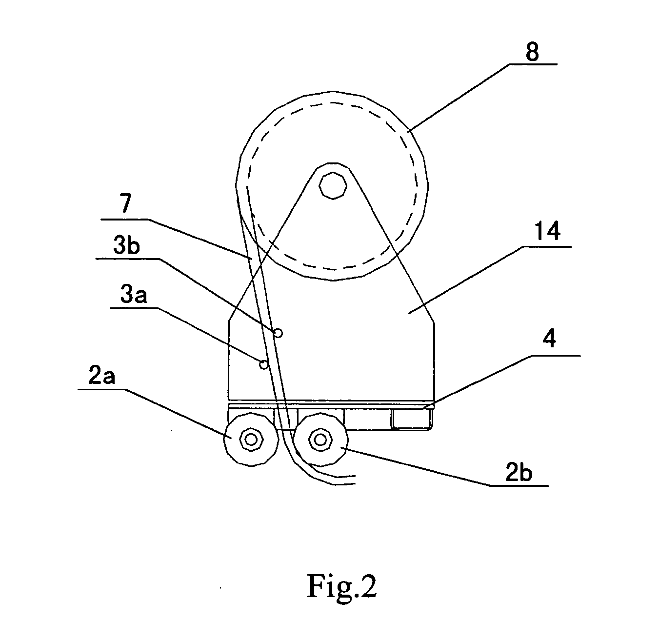
[0037] As shown in FIGS. 1 and 2, a reel apparatus 100 according to the embodiment of the present application comprises a base 4 and a rotatable drum 8 rotatably supported on the base 4, so that a linear material such as a cable 7 can be spooled onto or unspooled from the rotatable drum 8.

[0038] Preferably, the drum 8 is provided with rotation shafts 8a on both sides thereof (in FIG. 1, only a rotation shaft 8a on the right side is shown). A first bracket 14a and a second bracket 14b are disposed on the base 4 so as to support rotatably the rotation shafts 8a on both sides of the drum 8 respectively. For example, the first and second brackets 14a and 14b support the rotation shafts 8a through bearings 17 so as to reduce a resistance force to the r...


PUM


Abstract

A reel apparatus for a moveable system comprises a base disposed on the moveable system; a rotatable drum rotatably supported on the base onto which a cable can be spooled; a speed reducer for rotating the drum; a motor drive the speed reducer; a first transmission device coupled between the motor and the speed reducer; a coupling coupled between the speed reducer and the motor, when a load of the drum exceeds a predetermined torque, the coupling slips so as to limit a drive torque transmitted from the motor to the speed reducer to stop the drum; and an electrical connector connected at one end to a power cord of the moveable system and slidably contacted with the other end thereof with one end of the cable. With the present invention, a commercial power supply can be connected to the moveable system directly, thus reducing components of the conventional power supplying apparatus. At the same time, the cable sheath is prevented from being damaging and potential safety hazards are eliminated.

Description

BACKGROUND OF THE INVENTION [0001] 1. Technical Field of the Invention [0002] The present invention relates to a reel apparatus, and particularly to a reel apparatus for spooling and unspooling a linear material such as a cable used to supply commercial power to a moveable system. [0003] 2. Description of the Related Art [0004] When a moveable system such as a movable scanning system for inspecting a vehicle carrying containers operates, it is required to supply power from an external power supply. Generally, the moveable system is supplied with power from an electrical generator. However, in some situations, supplying power using the electrical generator is restrained by many conditions, so that a commercial power supply has to be used. [0005] The conventional commercial power supplying apparatus mainly comprises a current collector, a sliding contact means, and a cable dragging means which cooperate to enable the commercial power supply to a moveable system. [0006] However, the co...

Claims


Application Information

Patent Timeline
IPC IPC(8): H02G11/02
CPCB65H75/4486H02G11/02
Inventor CAO, CHENGXINJIANG, NANYU, WEIFENG
Owner NUCTECH CO LTD
Why Eureka
Try Eureka