Preparation of filler-metal weld rod by injection molding of powder

a technology of filler metal and weld rod, which is applied in the direction of welding/cutting media/materials, manufacturing tools, welding apparatus, etc., can solve the problems of incomplete alloying, achieve high precision in composition control of weld rod, and achieve convenient production. , the effect of convenient and economical approach

Inactive Publication Date: 2007-03-01
GENERAL ELECTRIC CO
View PDF26 Cites 1 Cited by
  • Summary
  • Abstract
  • Description
  • Claims
  • Application Information

AI Technical Summary

Benefits of technology

[0009] The present approach provides a method for producing filler-metal weld rod that is widely applicable. However, the process is most advantageously applied to weld rod wherein the filler metal is a difficult-to-work material such as a high-gamma prime nickel-base superalloy or a titanium aluminide, because there is no gross deformation of the weld rod required during the manufacturing process. The present approach produces a weight yield of usable weld rod, as compared with the weight of the starting material, of near 100 percent. There is excellent process economics and reduced cost of the weld rod. The quality of the weld rod is high, with low incidence of defects that can be transferred to the welded structure. New compositions may be readily prepared by the present approach.
[0016] The present approach provides a convenient and economical approach to producing filler-metal weld rod. Filler-metal weld rod of any composition that is available in powder form may be made, even of difficult-to-draw metals such as high-gamma prime nickel-base superalloys and intermetallics. Compositional control of the weld rod is highly precise. New compositions may be readily produced, without the extensive experimentation and process development required in most other processes when making weld rod of a new composition. The oxygen content of the final weld rod is below that expected from the oxygen contents of the starting materials, suggesting a chemical reaction and removal of the oxygen.

Problems solved by technology

Otherwise, some alloying is required during the processing or the use of the weld rod in a welding procedure, and there is a possibility of incomplete alloying although full alloying occurs during the subsequent welding operation.

Method used


Image

  • Preparation of filler-metal weld rod by injection molding of powder
  • Preparation of filler-metal weld rod by injection molding of powder
  • Preparation of filler-metal weld rod by injection molding of powder

Examples


Embodiment Construction

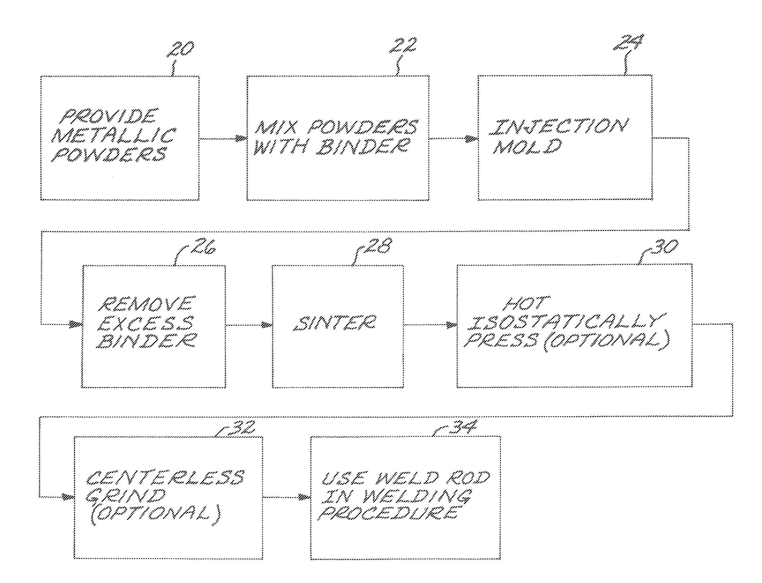
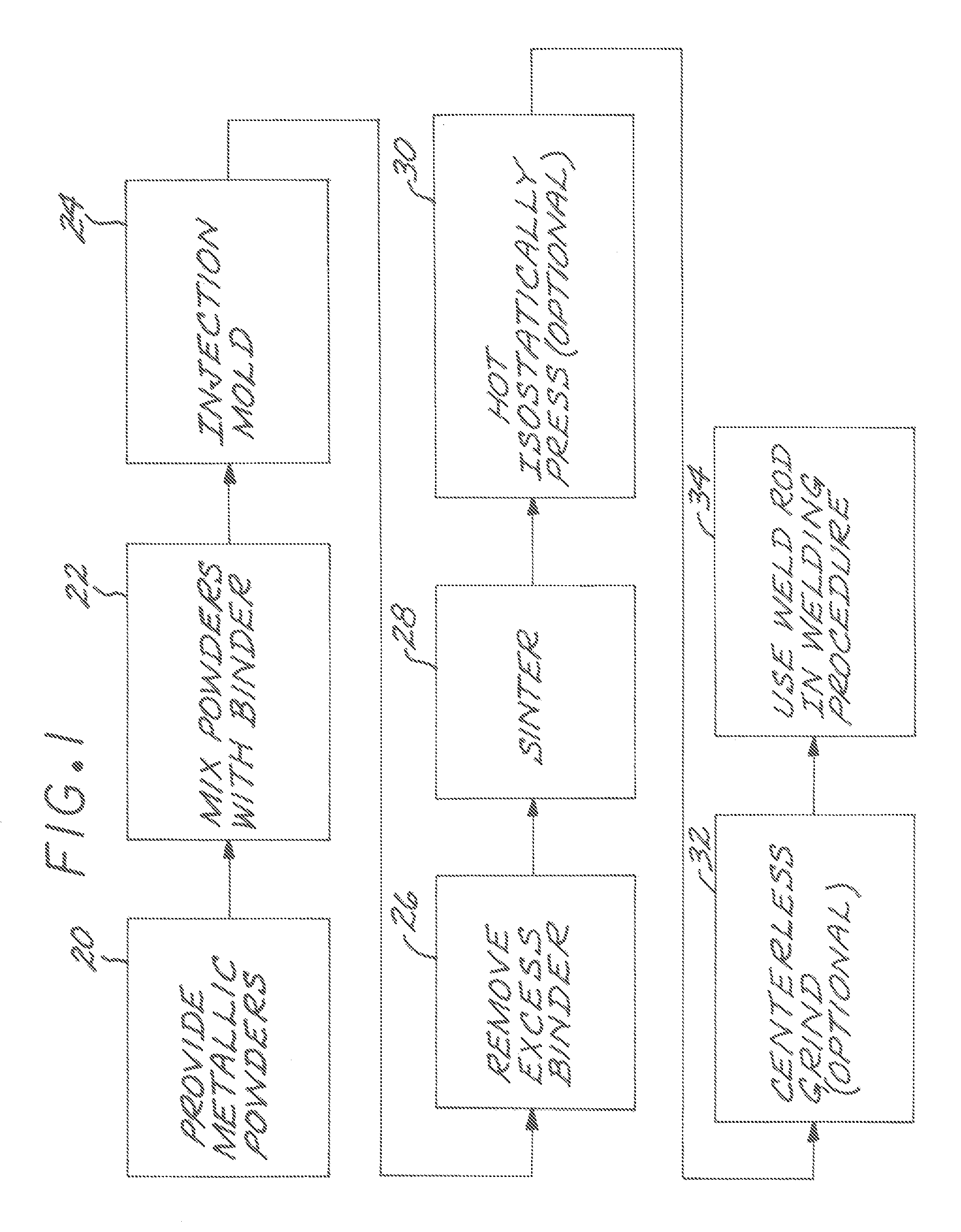
[0021]FIG. 1 depicts the steps in a method for preparing a filler-metal weld rod of a filler-metal composition. A mass of metallic powders is provided, step 20. The mass of metallic powders taken together have the filler-metal composition. The metallic powders are preferably prealloyed. That is, each powder particle has the net filler-metal composition as to metallic elements. Prealloyed metallic powders for compositions of interest are available commercially, or can be prepared specially by known techniques. The metallic powder particles may instead be of different compositions, but selected so that the net composition of all of the metallic powder particles taken together is the filler-metal composition of interest.

[0022] The present approach is operable to produce any of a wide range of filler-metal compositions. As long as prealloyed powders or powders who compositions can be combined to define a composition of interest are available, the present approach may be utilized. Howev...


PUM

PropertyMeasurementUnit
cylindrical diameteraaaaaaaaaa

Abstract

A filler-metal weld rod of a filler-metal composition is prepared by providing a mass of metallic powders, mixing the metallic powders with a temporary thermoplastic binder to form an injection-moldable mixture, and thereafter injection molding the injection-moldable mixture at an injection-molding temperature above the thermoplastic temperature of the thermoplastic binder to form an injection-molded rod. Any excess thermoplastic binder is removed from the injection-molded rod, and the injection-molded rod is thereafter sintered to form a filler-metal weld rod, with the temporary thermoplastic binder removed in the step of sintering.

Description

RELATED APPLICATIONS [0001] This application is a continuation of U.S. application Ser. No. 10 / 900,803 filed Jul. 27, 2004 the entirety of which is hereby incorporated by reference.FIELD OF THE INVENTION [0002] This invention relates to the preparation of filler-metal weld rod and, more particularly, to the preparation of weld rod of difficult-to-deform alloys. SUMMARY OF THE INVENTION [0003] In a form of welding, a metallic article to be welded is locally melted, and the melted metal is mixed with a second metal. The temperature is thereafter reduced so that the melted mixture solidifies. In one approach, the second metal is another article, so that the two articles are joined together. In another approach, the second metal is an overlay deposit that is also melted during the welding process, with the result that the first article is overlaid with the second metal. [0004] A filler metal may be used in either of these approaches. In the joining of two articles by welding, the filler...

Claims


Application Information

Patent Timeline
Patent Type & Authority Applications(United States)
IPC IPC(8): B23K35/22
CPCB22F3/225B22F2998/00B22F2998/10B23K35/3033B23K35/304B23K35/3086B23K35/325B23K35/40B22F1/0003B22F3/1021B22F3/15B22F1/00
Inventor KELLY, THOMAS JOSEPH
Owner GENERAL ELECTRIC CO
Why Eureka
Try Eureka