Image sensor

a technology of image sensor and image, which is applied in the direction of optical radiation measurement, radiation control device, instruments, etc., can solve the problems of difficult to realize a sufficient cutting function with respect to infrared rays with angles such as oblique incidence, difficulty in miniaturization of cameras, and difficulty in color separation in infrared range. achieve the effect of improving color performance properties

Inactive Publication Date: 2007-03-01
TOPPAN PRINTING CO LTD
View PDF2 Cites 29 Cited by
  • Summary
  • Abstract
  • Description
  • Claims
  • Application Information

AI Technical Summary

Benefits of technology

[0047] Thereby, the lower layer part under the lens of the image sensor can be made thinner. Thus, it is possible to improve color performing properties for obtaining the image sensor allowing the bright observation.

Problems solved by technology

However, since the organic color filter does not have an infrared ray cutting function, it is difficult to carry out the color separation in the infrared range.
Although the reflection type infrared ray cutting filter comprising the inorganic multi layer film has a high infrared ray cutting function with respect to an incident light in the direction perpendicular to the filter surface, it is difficult to realize a sufficient cutting function with respect to an infrared ray with an angle such as the oblique incidence.
However, in the case of using the absorbing type infrared ray cutting filter, since the absorbing type infrared ray cutting filter has a thickness of about 1 to 3 mm, the miniaturization of a camera, or the like may be difficult.
Moreover, in the case of assembling the infrared ray cutting filter in a lens system as a camera part, a cost reduction may be difficult.
In the case where the infrared ray is cut with respect to all the light receiving elements included in the image sensor, the green sensitivity, and in particular, the red sensitivity may be deteriorated.

Method used


Image

  • Image sensor
  • Image sensor
  • Image sensor

Examples


first embodiment

[0103] In this embodiment, an image sensor included in, for example, a digital camera, a portable phone, a video camera, a linear sensor, a scanner, or the like will be explained.

[0104] In this embodiment, the image sensor has color filters disposed on a light incident side of light receiving elements, for allowing an observation of color components of an observation target.

[0105] In this embodiment, the image sensor comprising compensating filters having transmittances in an infrared range higher than a transmittance in a visible light wavelength range in addition to spectral filters used for extracting each of green, blue and red components out of an incident light will be explained.

[0106] As the spectral characteristics of the compensating filters, transmission restraining characteristics are provided in the visible light wavelength range and transmission characteristics in the infrared range.

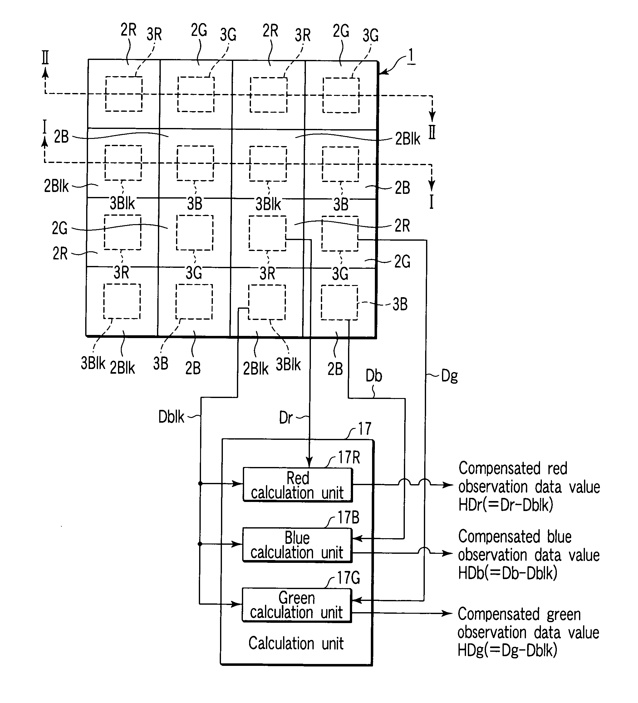
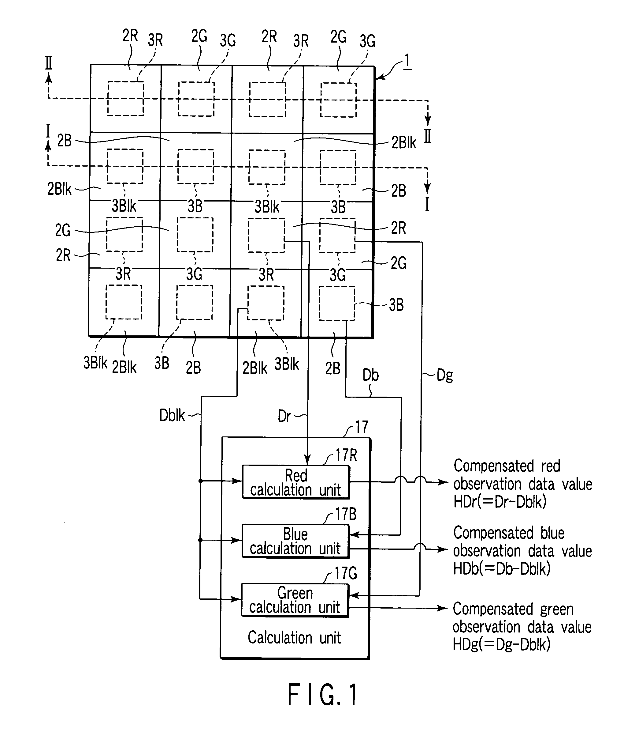
[0107]FIG. 1 is a front view showing an example of an installation state of three co...

second embodiment

[0190] In this embodiment, a modified example of the above-mentioned first embodiment will be explained.

[0191] In the above-mentioned first embodiment, for reducing the difference between the transmittance of the spectral filter 2G and the transmittance of the spectral filter 2B in the infrared range and adjusting the transmittance in the infrared range, the characteristic of restraining the transmittance in the wavelength range including 780 nm is provided in the resin layer 7.

[0192] On the other hand, in this embodiment, the green spectral filter 2G itself is provided with a characteristic of restraining the transmittance in the wavelength range including 780 nm as the infrared range. Thereby, the color separation can be enabled in the same manner as in the above-mentioned first embodiment.

[0193] In order to restrain the transmittance in the wavelength range including the 780 nm wavelength in the infrared range, an organic pigment may be added to the green spectral filter 2G. M...

third embodiment

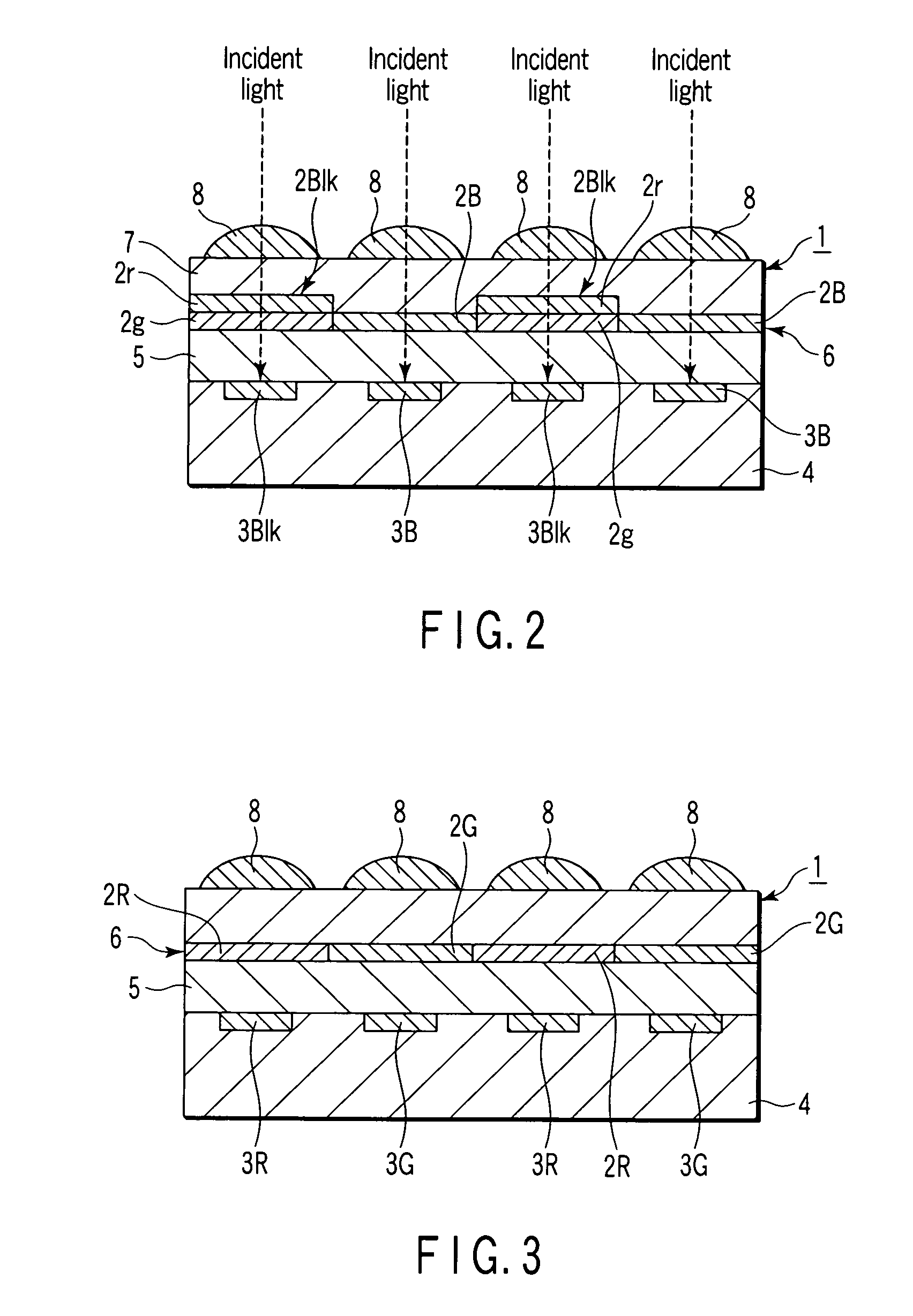
[0198] In this embodiment, a modified embodiment of the above-mentioned first and second embodiments will be explained. In the above-mentioned first and second embodiments, the compensating filter 2Blk comprises the green filter element 2g and the red filter element 2r.

[0199] On the other hand, in this embodiment, instead of the compensating filter 2Blk, a compensating filter comprising a blue filter element and a red filter element is used.

[0200]FIG. 8 is a front view showing an example of an arrangement state of the three color spectral filters 2G, 2B, 2R and the compensating filter in the image sensor according to this embodiment. In FIG. 8, an example viewed from the light incident side is shown. In FIG. 8, the calculation unit 17 is omitted.

[0201]FIG. 9 is a diagram showing an example of a cross section of the image sensor. FIG. 9 shows the cross section taken along a line III-III of FIG. 8.

[0202] The image sensor 9 comprises a compensating filter 10Blk instead of the compe...


PUM


Abstract

In an embodiment example of the present invention, an image sensor comprises a filter used for an extraction of a specific color component of an incident light, a light receiving element which observes the incident light via the filter, a compensating filter having a transmission restraining characteristic in a visible light wavelength range and a transmission characteristic in a wavelength range on a longer wavelength out of the visible light wavelength range, and a compensating light receiving element which observes the incident light via the compensating filter for compensating an observation result by the light receiving element.

Description

CROSS-REFERENCE TO RELATED APPLICATIONS [0001] This is a Continuation Application of PCT Application No. PCT / JP2005 / 011275, filed Jun. 20, 2005, which was published under PCT Article 21(2) in Japanese. [0002] This application is based upon and claims the benefit of priority from prior Japanese Patent Application No. 2004-193151, filed Jun. 30, 2004, the entire contents of which are incorporated herein by reference. BACKGROUND OF THE INVENTION [0003] 1. Field of the Invention [0004] The present invention relates to an image sensor comprising a light receiving element. [0005] 2. Description of the Related Art [0006] A light receiving element converts a light to an electric signal. For example, a light receiving element such as a CMOS or a CCD has a high sensitivity even in a range outside a visible light wavelength range (for example, a wavelength range of 400 nm to 700 nm) as the human visible range, in particular, it also has a high sensitivity in a wavelength range on the wavelengt...

Claims


Application Information

Patent Timeline
Patent Type & Authority Applications(United States)
IPC IPC(8): H01L27/00G01J3/50
CPCG02B3/0018G02B3/0056G02B5/201H04N9/045H01L31/02162H01L31/0232H01L27/14621H01L31/02327H01L27/14627H04N25/134H01L27/146
Inventor FUKUYOSHI, KENZOKITAMURA, SATOSHI
Owner TOPPAN PRINTING CO LTD
Why Eureka
Try Eureka