Optical encoder and controller for the same

a technology which is applied in the field of optical encoder and controller for the same, can solve the problems of limited resolution of commercially available optical encoder wheels, increased resistors, and limited first method effect, and achieves the effect of high resolution and higher resolution

Inactive Publication Date: 2007-03-01
DELTA ELECTRONICS INC
View PDF3 Cites 10 Cited by
  • Summary
  • Abstract
  • Description
  • Claims
  • Application Information

AI Technical Summary

Benefits of technology

[0024] The present invention is intended to provide a DSP-based optical encoder performing interpolation by inverse trigonometric function in original analog signal and counting by hysteresis comparison, thus achieving high resolution.
[0025] Accordingly, the present invention provides an optical encoder and a controller for the same. The optical encoder comprises a controller for processing output signals of an optical sensor. The optical sensor generates output periodic signals with quadrature phase difference after receiving light passing a glass plate with etched pattern. The controller comprises a pair of analog amplifiers for amplifying quadrature periodical output signals of the optical sensor,...

Problems solved by technology

However, the commercially available optical encoder wheel has limited resolution even though interpolation is used.
The first method has limited effect because manufacture difficulty and diffraction phenomenon.
However, the amount of resistors is increased and the accuracy of the resistors is demanding when more pa...

Method used


Image

  • Optical encoder and controller for the same
  • Optical encoder and controller for the same
  • Optical encoder and controller for the same

Examples


Embodiment Construction

[0035]FIG. 6 shows a schematic view of an optical encoder 10 according to a preferred embodiment of the present invention. The optical encoder 10 mainly comprises a coherent light source 200 such as a laser lamp, a glass plate 210 with etched pattern, a photo mask 200, a light sensor 240 and a controller 100 (not shown). The glass plate 210, for example, has pattern with 2500 marks per turn. Namely, there are 2500 A, B phase signals with 90°phase difference.

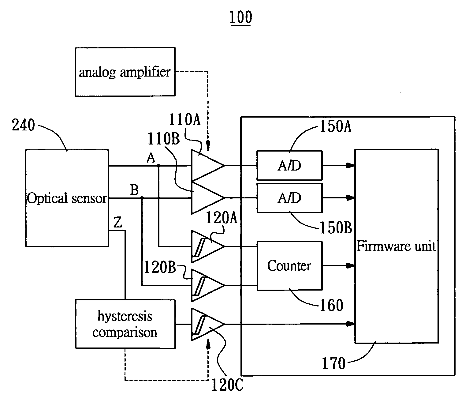
[0036]FIG. 7 is block diagram of the controller 100, which processes a detected signal from the light sensor 240 to obtain a displacement information of the glass plate 210. The controller 100 comprises a first analog amplifier 110A and a second analog amplifier 110B electrically connected to the light sensor 240, a first hysteresis comparator 120A, a second hysteresis comparator 120B and a third hysteresis comparator 120C electrically connected to the light sensor 240. Moreover, the controller 100 further comprises a first ADC ...


PUM


Abstract

An optical encoder includes a controller electrically connected to an optical sensor to discriminate displacement information of a glass disc. The controller comprises a pair of analog amplifiers for amplifying quadrature periodical output signals of the optical sensor, a pair of A/D converters electrically connected to the analog amplifiers for digitalizing the output of the analog amplifiers, a pair of hysteresis comparators electrically connected to the optical sensor for performing hysteresis comparison for the output of the optical sensor, an up/down counter electrically connected to the pair of hysteresis comparators for up/down counting the output of the hysteresis comparators and a firmware unit electrically connected to the pair of A/D converters and the up/down counter for performing interpolation for the quadrature periodical output signals and counting for the hysteresis compared signals. Therefore, optical encoded result of higher resolution can be achieved.

Description

BACKGROUND OF THE INVENTION [0001] 1. Field of the Invention [0002] The present invention relates to an optical encoder and a controller for the same, especially to a DSP-based optical encoder performing interpolation by inverse trigonometric function in original analog signal and counting by hysteresis comparison, thus achieving high resolution. [0003] 2. Description of Prior Art [0004] The AC servomotor generally comprises an optical encoder wheel to sense angle information of a rotator, this angle information can be used to determine an electromagnetic field for driving stator current. Therefore, the speed of the AC servomotor can be precisely controlled. The noise of the AC servomotor can be advantageously reduced if the optical encoder wheel can provide higher resolution. However, the commercially available optical encoder wheel has limited resolution even though interpolation is used. [0005] The conventional ways to enhance resolution for grating type optical encoder wheel inc...

Claims


Application Information

Patent Timeline
IPC IPC(8): G01J3/50
CPCG01D5/24404H03M1/303H03M1/202G01D5/3473
Inventor TSAI, CHING-HSIUNGCHEN, JIAN-DALIN, MENG-CHANGLIN, CHENG-PING
Owner DELTA ELECTRONICS INC
Why Eureka
Try Eureka