Spark plug

Inactive Publication Date: 2007-03-01
NGK SPARK PLUG CO LTD
View PDF9 Cites 28 Cited by
  • Summary
  • Abstract
  • Description
  • Claims
  • Application Information

AI Technical Summary

Benefits of technology

[0007] It is therefore an object of the present invention to provide a spark plug capable of holding a ceramic insulator in a metal shell securely without causing problems such as a break in the cera

Problems solved by technology

This results in various problems such as slipping of the ceramic insulator out of the metal shell and combustion gas leakage from between the metal shell and the ceramic insulator.
If the shell end portion is crimped onto the insulator shoulder portion so as to attain a higher coverage ratio, the inner edge of the crimped shell portion may come into contact with the ceramic insulator and cause a break in the ceramic insulator.
In the case of the small-diameter spark plug, however, the metal packing cannot be placed in a proper position inside of the metal shell when the inner diameter of the metal packing is large relative to the outer diameter of the rear in

Method used


Image

  • Spark plug
  • Spark plug
  • Spark plug

Examples


experiment 1

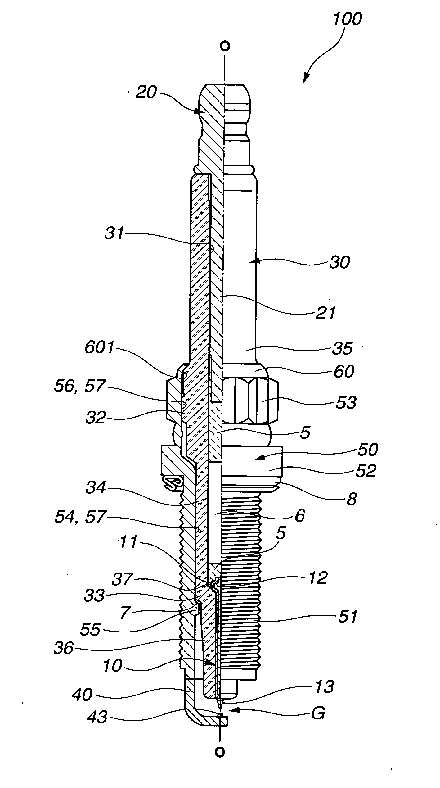
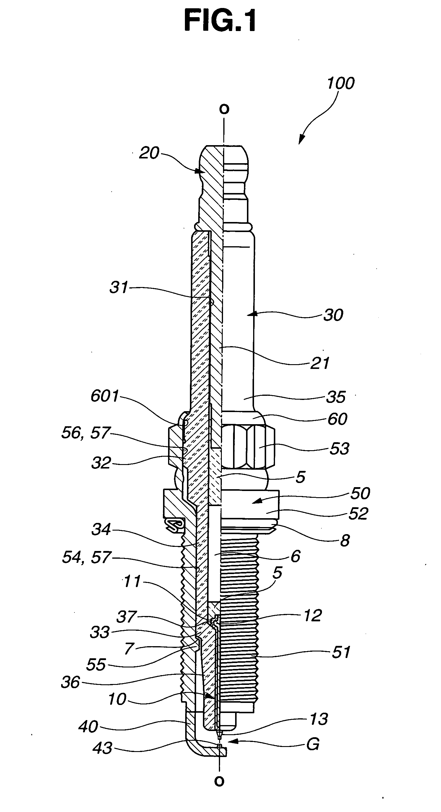
[0054] Five types of samples of the spark plug 100 (5 samples for each type, 25 samples in total) were produced in the same way as described above by varying the length of the rear end portion 60 of the metal shell 50 (as measured before the crimping process). The plug components of the samples used were those for general-purpose spark plugs. Further, the crimping process was performed using the same crimping jig through the application of a tightening torque of 25 N·m so as to attain the same bending degree (angle) for all of the samples. The dimensions of the samples are indicated in TABLE 1.

[0055] Each of the samples was tested for the gas tightness between the metal shell 50 and the ceramic insulator 30 as follows. In the test sample, a gas hole was made through the metal shell 50 at a position between the plug attachment portion 52 and the tool engagement portion 53 to communicate with the through-hole 57. A flow of air gas was injected into the test sample from its front side...

experiment 2

[0057] Seven types of samples of the spark plug 100 (5 samples for each type, 35 samples in total) were produced in the same way as in Experiment 1, except that the crimping process was performed using different crimping jigs to vary the shape of the crimped shell portion 60 and the area of the contact region 602 of the crimped shell portion 60 although the rear end portion 60 of the metal shell 50 was set at the same length for all of the test samples. The dimensions of the samples are indicated in TABLE 2.

[0058] The samples were tested for the gas tightness between the metal shell 50 and the ceramic insulator 30 in the same way as in Experiment 1. The test results are indicated in TABLE 2 and FIG. 7. (In FIG. 7, the numbers assigned to the plot points represent the sample types.)

[0059] The samples were also tested for the power of the crimped shell portion 60 to hold the ceramic insulator 30 as follows. The test sample was fixed on a sample stage by screwing the threads 51 into ...

experiment 3

[0061] Seven types of samples of the spark plug 100 (5 samples for each type, 35 samples in total) were produced in the same way as in Experiment 2. The dimensions of the test samples are indicated in TABLE 3.

[0062] The samples were subjected to Charpy test as follows according to JIS B7722 in order to evaluate the resistance of the ceramic insulator 3 to breaking. The test sample was fixed on a sample stage by screwing the threads into a threaded vertical through-hole of the sample stage with a front end of the spark plug directed downward. A hammer was fastened pivotally about a point above the spark plug 100 on the spark plug axis O. A head of the hammer was lifted to some height, and then, released to fall freely to collide with a part of the ceramic insulator 30 located at a distance of about 1 mm from the insulator rear end. The above test procedure was repeated by gradually increasing the hammer head lifting angle by given degrees. The breaking energy of the ceramic insulato...


PUM

PropertyMeasurementUnit
Lengthaaaaaaaaaa
Fractionaaaaaaaaaa
Angleaaaaaaaaaa

Abstract

A spark plug is provided with a metal shell and a ceramic insulator to support therein a center electrode. The ceramic insulator includes a front portion with a stepped outer surface, a middle portion, a rear portion and a shoulder portion defined between the middle and rear portions. A difference between the outer diameters of the middle and rear portions of the ceramic insulator is 1.8 mm or smaller. The metal shell includes a radially inward protrusion to retain thereon the stepped outer surface of the ceramic insulator and a rear end portion crimped onto the shoulder portion of the ceramic insulator. An inner circumferential surface of the crimped shell portion has a region held in contact with the insulator shoulder portion with a radially innermost point of the crimped shell portion being spaced radially apart from the ceramic insulator and axially apart from the insulator shoulder portion.

Description

BACKGROUND OF THE INVENTION [0001] The present invention relates to a spark plug, particularly of small-diameter type, for use in an internal combustion engine. Hereinafter, the term “front” refers to a spark discharge side with respect to the direction of the axis of a spark plug, and the term “rear” refers to a side opposite to the front side. [0002] A spark plug of an internal combustion engine generally includes a metal shell and a ceramic insulator supporting therein a center electrode and a terminal electrode insulatively. The ceramic insulator is held in the metal shell by seating a stepped outer surface portion of the ceramic insulator against a protruded inner surface portion of the metal shell and crimping a rear end portion of the metal shell onto a shoulder portion of the ceramic shell. There are several methods for crimping the metal shell onto the ceramic insulator. In one crimping method, the metal shell is deformed by cold forging with an insulating powder material f...

Claims


Application Information

Patent Timeline
IPC IPC(8): H01T13/20
CPCH01T13/36Y10T29/49231H01T21/02
Inventor MORIBE, MAISUZUKI, AKIRA
Owner NGK SPARK PLUG CO LTD
Why Eureka
Try Eureka