Method of evaluating fiber pmd using potdr trace

a fiber and trace technology, applied in the field of optical fibers, can solve the problems of limiting the transmission rate of pulses or the maximum distance of concatenated fiber medium, affecting the economic benefits of fiber makers, and causing significant financial losses

Inactive Publication Date: 2007-03-01
CORNING INC
View PDF19 Cites 14 Cited by
  • Summary
  • Abstract
  • Description
  • Claims
  • Application Information

AI Technical Summary

Benefits of technology

[0020] Thus, we have found that backscatter intensity traces from large linewidth pulses allow an analysis which reveals the existence of elevated PMD in an optical fiber, and moreover allow the detection of relatively short length sect

Problems solved by technology

The pulse spreading from PMD can introduce errors into the data transmission, effectively limiting the transmission rate of the pulses or the maximum distance of the concatenated fiber medium.
Although fiber outliers usually represent a very small percentage of the whole population of newly made fibers, the effect of such fibers can be very detrimental.
Fiber PMD failure identified at a cable plant can also incur significant financial loss to the fiber makers.
However, a common feature of the above known methods is that they are e

Method used


Image

  • Method of evaluating fiber pmd using potdr trace
  • Method of evaluating fiber pmd using potdr trace
  • Method of evaluating fiber pmd using potdr trace

Examples


example 1

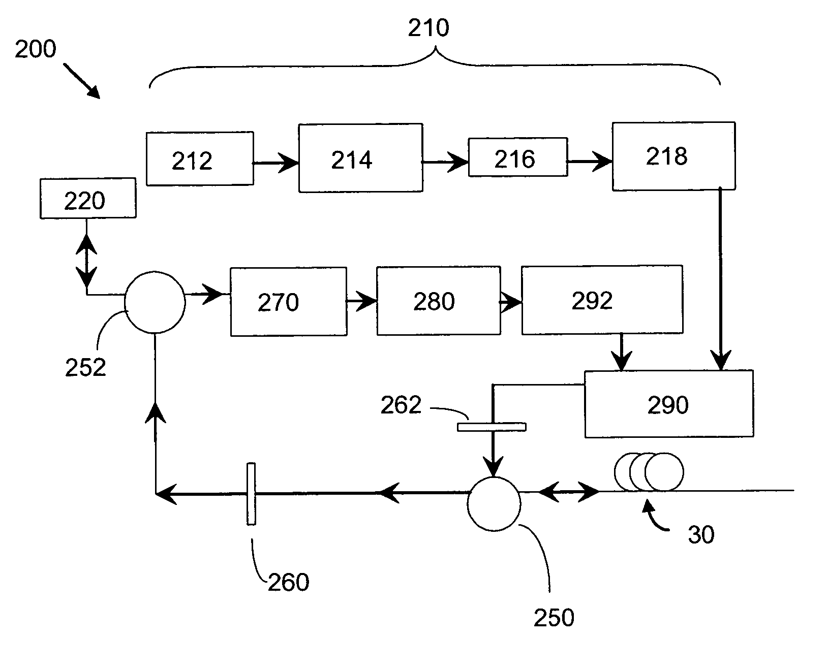
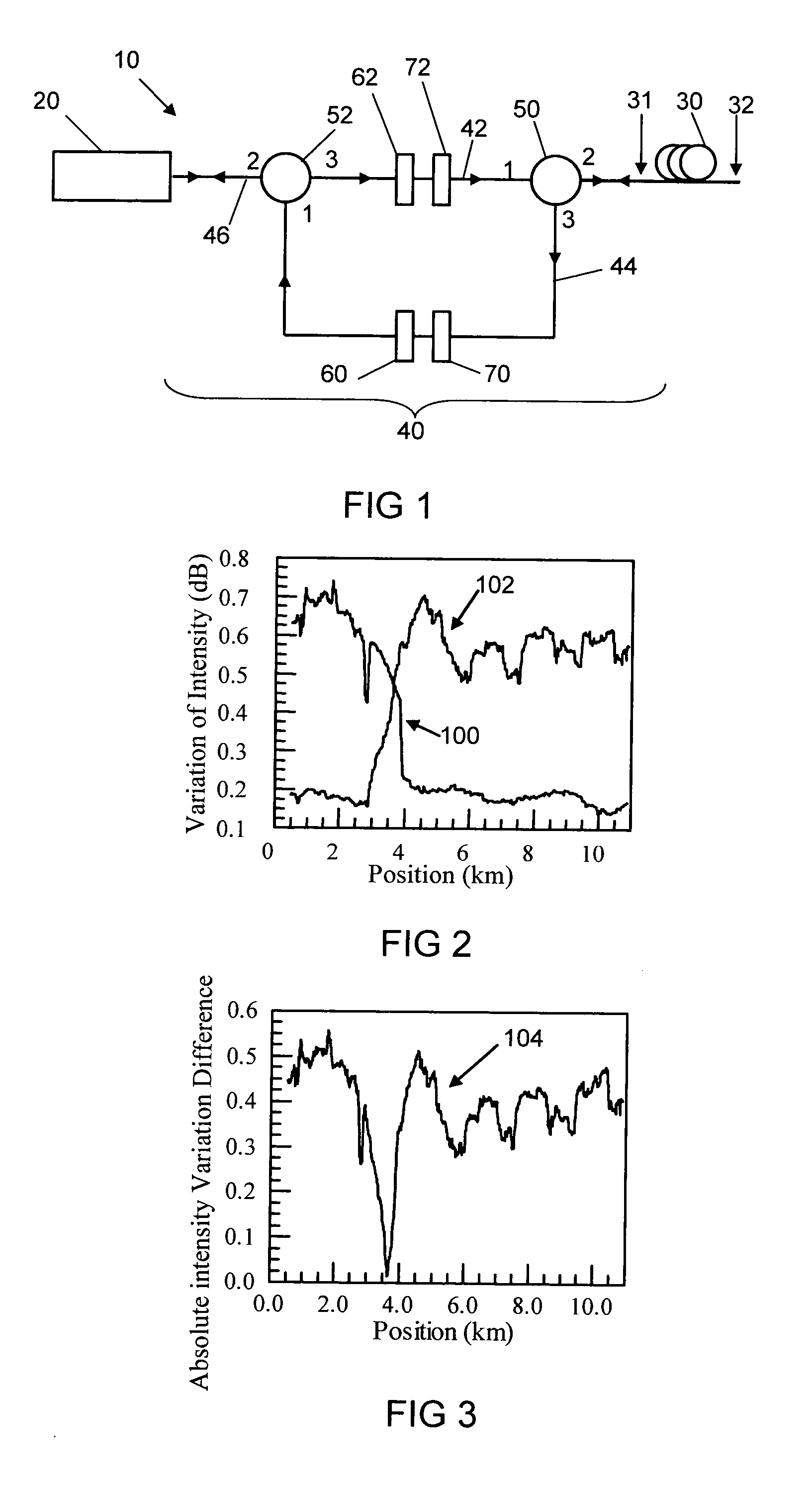
[0043] An optical fiber test apparatus 10 as illustrated in FIG. 1 was utilized to test a 12 km length of optical fiber to demonstrate an embodiment of the present invention. A first end 31 of the fiber 30 was optically coupled to the optical path 40. The pulse width of the pulses emitted from POTDR 20 were 100 ns. Known OTDRs typically provide linewidths of between 1 nm and 2 nm. The polarizing angle of polarizer 60 and of polarizer 62 was fixed for all measurements. The variation of intensity of the first POTDR trace was analyzed by determining the standard deviation of the first POTDR trace over a sliding window of data from the first POTDR trace and moving the window of data lengthwise along the length of the fiber while continuing to analyze the variation of intensity, to obtain a first variation of intensity trace 100, as seen in FIG. 2. The first end 31 of the fiber 30 was detached from the optical path 40, and the second (opposite) end 32 of the fiber 30 was optically couple...

example 2

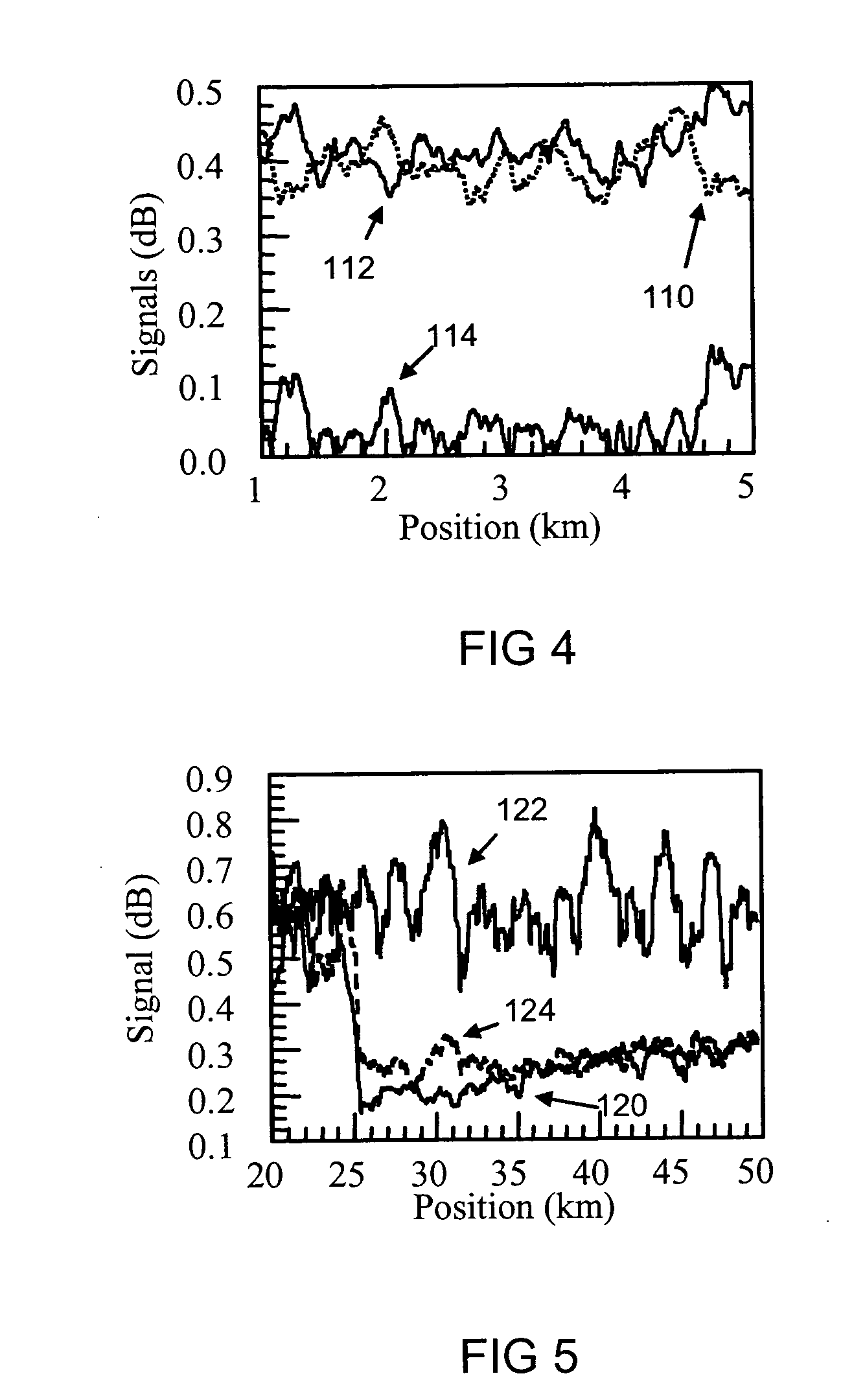
[0050]FIG. 4 shows first and second variation of intensity traces 110, 112, as well as the absolute intensity variation difference trace 114, for an optical fiber which has PMD values less than 0.1 ps / km1 / 2 everywhere across its length. The absolute intensity variation difference trace 104 is less than 0.12 dB across the entire length of the fiber.

[0051] Implementation of the present invention requires that the orientations of polarization angles of the first and second polarized input light pulses are not aligned with any of the birefringent axes of the optical fiber. That is, the state of polarization of the light incident on the fiber under test, or the defective fiber with highly elevated PMD, is not linearly polarized and not well aligned with one of the two birefringent axes of the optical fiber. In the rare event that the incident light on the fiber is linearly polarized and its orientation is aligned with one of the birefringent axes, the presence of elevated PMD may not be...

example 3

[0052]FIG. 5 schematically illustrates the variation of intensity of traces taken from a 50 km length of optical fiber into which first, second, and third polarized input light pulses were sent into the same end of an optical fiber via an apparatus such as shown in FIG. 1, wherein polarizer 62 was set to three different polarizer angles of 0 degrees, 45 degrees, and −45 degrees corresponding to the first, second, and third polarized input light pulses, and respective backscatter intensity traces were obtained, and first, second, and third variation of intensity traces, 120, 122, and 124 respectively, were obtained. As seen in FIG. 5, the first and third traces 120 and 124 indicate that a PMD defect is situated at a location of 25 km, while such location is not determinative from the second trace 122. Thus, two variation of intensity traces correctly capture the location of the PMD defect, while one trace misses the location, where we believe that the state of polarization of the sec...


PUM


Abstract

A method for screening fiber polarization mode dispersion using a polarization optical time domain reflectometer is disclosed. A pulse radiation is emitted into an end of the fiber under test, and the backscattered radiation is measured by the POTDR and used to obtain an OTDR trace. A pulse radiation is emitted into an opposite end of the fiber under test, and the backscattered radiation is measured by the POTDR and used to obtain another OTDR trace. Either one or both traces are analyzed to compare the variation of intensity of signals along the length of the fiber, the variation in signals relating to the PMD along the length of the fiber.

Description

BACKGROUND OF THE INVENTION [0001] 1. Field of the Invention [0002] The present invention relates generally to optical fibers, and particularly to a method for identifying optical fibers which exhibit elevated polarization mode dispersion (PMD). [0003] 2. Technical Background [0004] PMD is an important factor in the design of state-of-art fiber optic transmission systems. The effect of PMD in fiber systems is evident when, after propagating a sufficient distance in the network, one digital pulse may spread in the time domain and become indistinguishable from a nearby pulse. The pulse spreading from PMD can introduce errors into the data transmission, effectively limiting the transmission rate of the pulses or the maximum distance of the concatenated fiber medium. Polarization mode dispersion (PMD) can be a major limitation for high data rate optical communications systems and is thus an important fiber attribute that fiber manufacturers monitor closely. One notorious aspect of fiber...

Claims


Application Information

Patent Timeline
IPC IPC(8): G01N21/00G01J4/00
CPCG01M11/3181
Inventor CHEN, XINHERON, NICOL ALEXANDER
Owner CORNING INC
Why Eureka
Try Eureka