Measuring system and screening method for thermal conductive efficiencies of thermal conductive devices

a technology of thermal conductive devices and measuring systems, which is applied in the direction of heat measurement, material flaw investigation, instruments, etc., can solve the problems of only obtaining a thermal conductive efficiency by means of a method, and the engineering of this field is extremely difficult, so as to achieve stable reproducibility, resolution and reliability, and reduce the measurement time. , the effect of reducing manpower and time cos

Active Publication Date: 2007-03-01
YEH CHIANG TECH CORP
View PDF16 Cites 32 Cited by
  • Summary
  • Abstract
  • Description
  • Claims
  • Application Information

AI Technical Summary

Benefits of technology

[0012] Another object of the present invention is to provide a screening method for the thermal conductive efficiencies of thermal conductive devices. In the case of confirming the cooling curve (cooling speed) of a standard sample in conjunction with the above-stated measuring system, the object of screening the thermal conductive efficiencies of the thermal conductive devices is achieved by using the c

Problems solved by technology

Since more transistors need to be contained in a limited space and more heat thus increased to vary the work functions of the electronic devices, this will cause an extremely challenge to engineers in this area.
Therefore, how to rapidly and effectively ensure the efficiency of the heat pipe by a measuring method is a main issue which needs to be studied.
Such measuring method only obtains a thermal conductive efficiency of the heat pipe at a specific heating power each time.
So, it is quite time consuming.
Therefore, it is frequently found in practice that when the heating terminal reaches the set temperature T1, immedi

Method used


Image

  • Measuring system and screening method for thermal conductive efficiencies of thermal conductive devices
  • Measuring system and screening method for thermal conductive efficiencies of thermal conductive devices
  • Measuring system and screening method for thermal conductive efficiencies of thermal conductive devices

Examples


Embodiment Construction

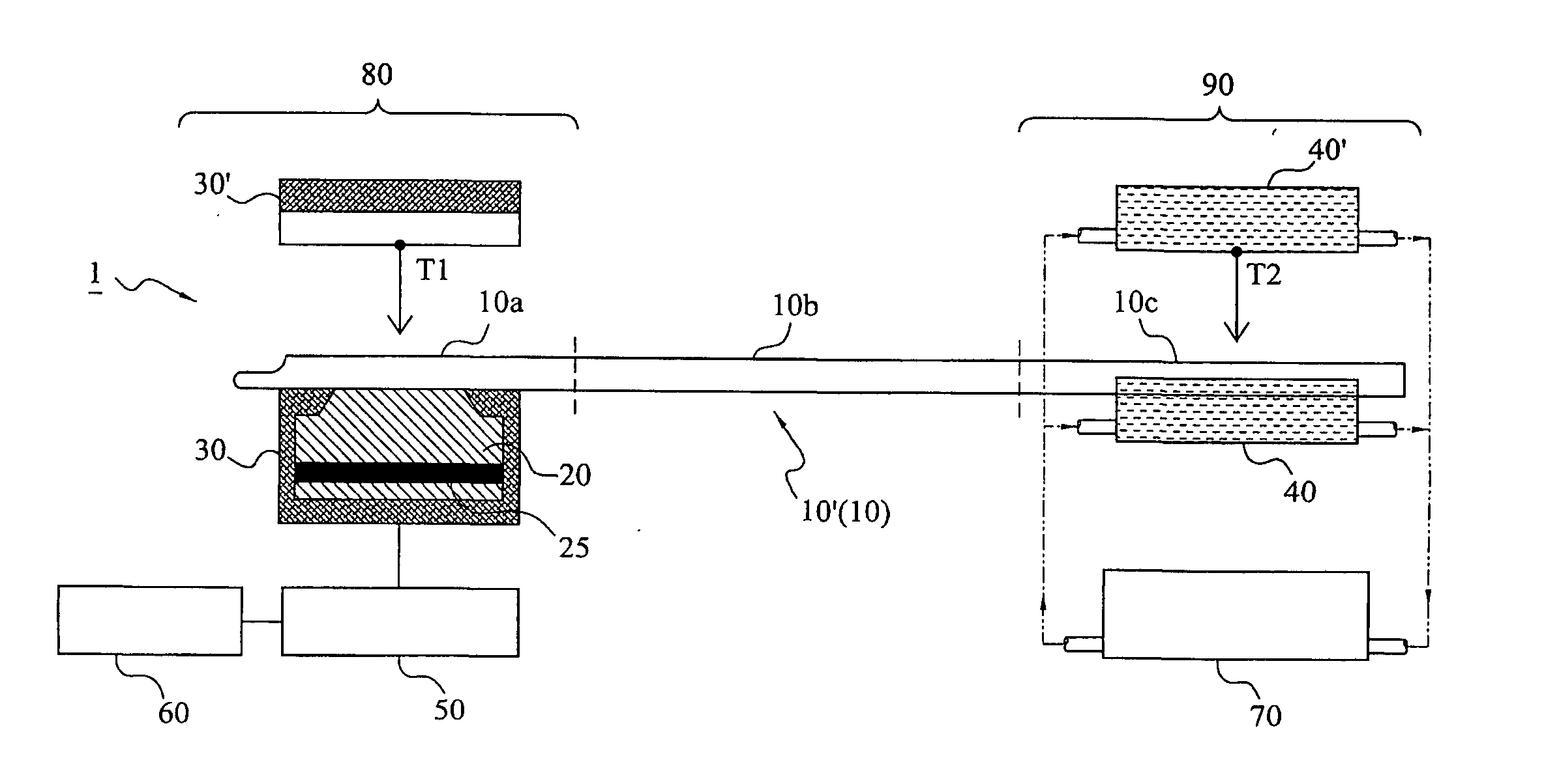
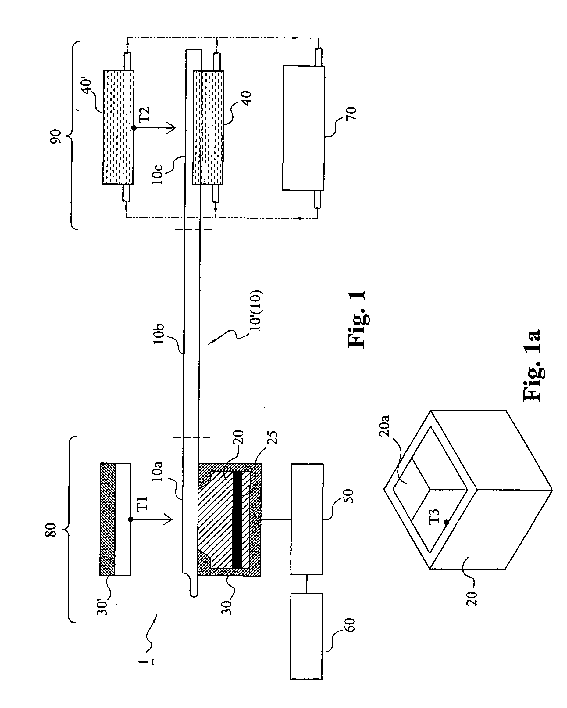
[0017] A measuring system and a screen method for the thermal conductive efficiencies of thermal conductive devices according to the present invention is to rapidly measure the thermal conductive efficiencies (for example, temperature difference ΔT, contact thermal resistance R and maximum thermal conductive quantity Qmax, etc.) of thermal conductive devices (for example, heat pipes, heat spreader, heat sinks, etc.) so as to attain the objects of fast quantification and screening. In the following embodiment, a heat pipe to be measured 10′ is used to further explain the technical features of the present invention. The embodiment is merely a preferred example, and is not used to limit the scope of the present invention. The present invention can become more fully understood from the following detailed descriptions with reference to the accompanying drawings.

[0018] First, referring to FIG. 1, a schematic view of a measuring system 1 for the thermal conductive efficiencies of thermal ...


PUM


Abstract

The measuring system generates a temperature difference between a heating terminal and a terminal conductive device by setting the temperature of a metal heated block at the heating terminal and the temperature of a heat dissipating water jacket at a heat dissipating terminal, and judges the thermal conductive capability of the thermal conductive device by comparing the cooling speed of the metal heating bock to obtain a relative power value according to the variation of heat quantity of the metal heated block in practical temperature reduction process. The maximum thermal conductive quantity (Qmax value) of the thermal conductive device can be rapidly obtained by parameter conversion with respect to the maximum power value. In the case of confirming the cooling curve (cooling speed) of a standard sample, the object of screening the thermal conductive efficiencies of the thermal conductive devices can be achieved by using the cooling curve.

Description

BACKGROUND OF THE INVENTION [0001] 1. Field of the Invention [0002] The present invention relates to a measuring system and a screening method for the thermal conductive efficiencies of thermal conductive devices. In particular, the present invention is to rapidly measure the thermal conductive efficiencies of thermal conductive devices (for example, heat pipes, heat spreaders, heat sinks, etc.) so as to attain the object of screening the thermal conductive efficiencies of the thermal conductive devices, and thus can greatly reduce manpower and time cost and meet the requirements of stable reproducibility, resolution and reliability. [0003] 2. Description of the Related Art [0004] With the trends of micro-miniaturization and multi-function of electronic products, it will bring devices and systems significant influences. Since more transistors need to be contained in a limited space and more heat thus increased to vary the work functions of the electronic devices, this will cause an ...

Claims


Application Information

Patent Timeline
IPC IPC(8): G01N25/18
CPCG01N25/18
Inventor LEE, KE-CHINLIN, CHEN-CHUANCHIN, CHI-TEWU, LI-KAI
Owner YEH CHIANG TECH CORP
Why Eureka
Try Eureka