Waveguide for plastics welding using an incoherent infrared light source

a waveguide and infrared light technology, applied in the field of plastics welding, can solve the problems of increased production costs, high heat produced by conventional laser systems, reflectors that have failed to reliably and efficiently direct infrared energy to the specific weld area, etc., and achieve the effect of reducing infrared energy

Inactive Publication Date: 2007-03-01
BRANSON ULTRASONIC CORP
View PDF54 Cites 23 Cited by
  • Summary
  • Abstract
  • Description
  • Claims
  • Application Information

AI Technical Summary

Benefits of technology

[0010] Masking has been used to try to minimize the infrared energy from reaching areas not to be melted. Although masking successfully prevents the infrared light from reaching a

Problems solved by technology

However, the heat produced by conventional laser systems often is expensive, which leads to increased production costs.
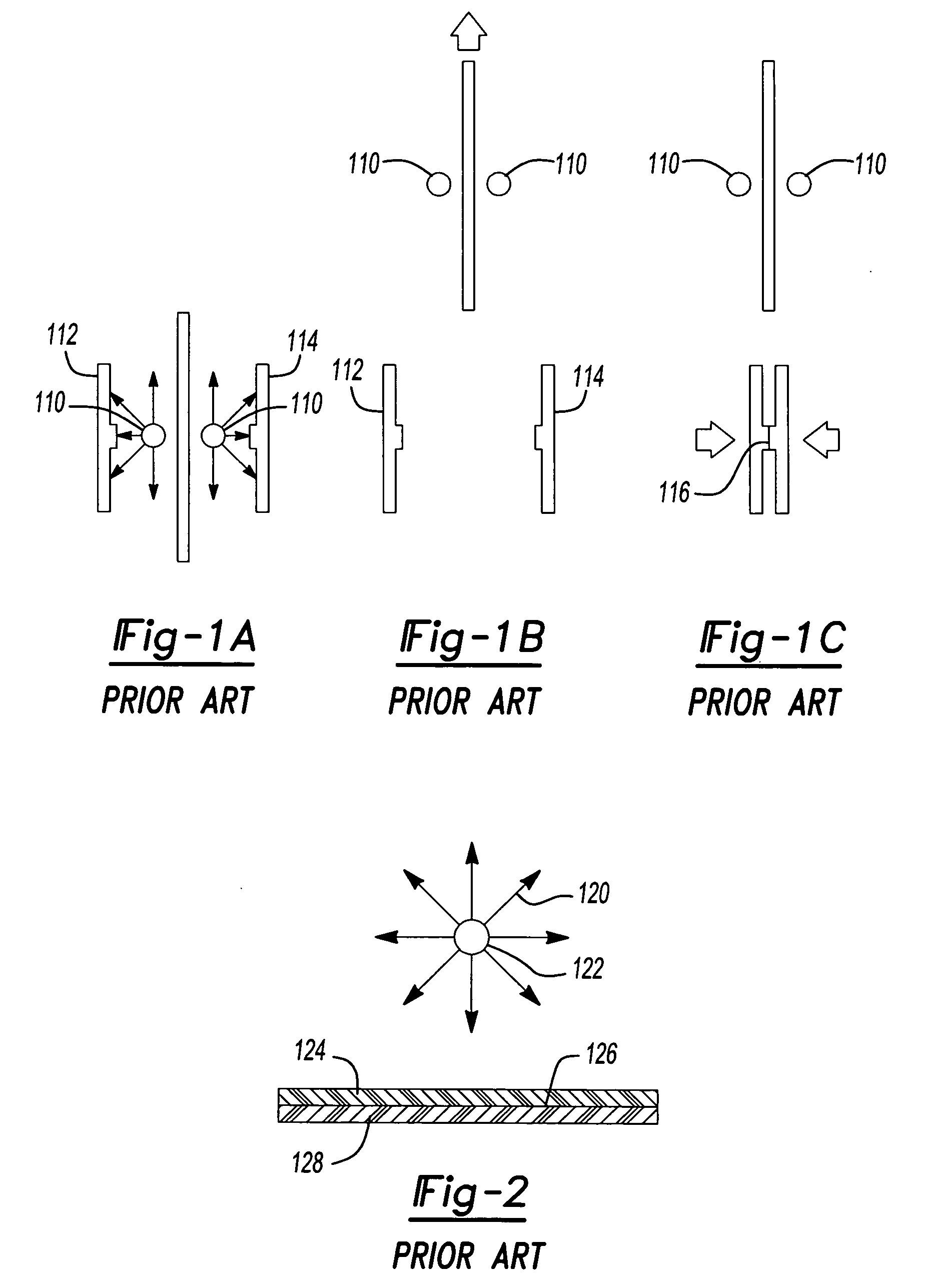
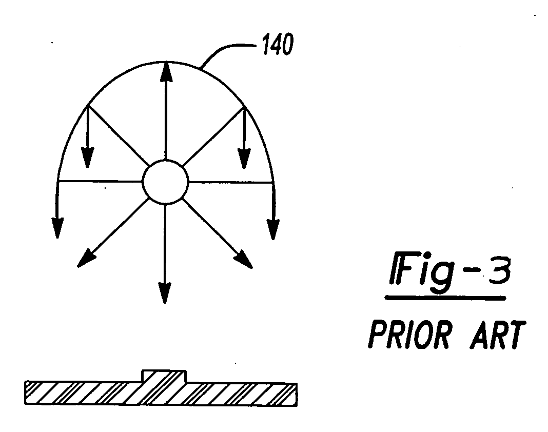
As seen in FIG. 3, the use of parabolic or elliptical reflectors 140 to try to direct this energy to a specific weld has been attempted, however, such reflectors have failed to reliably and efficiently direct this energy to the specific weld area.
Parabolic and elliptical reflectors do concentrate about fifty percent (50%) of the infrared light, but the other fifty percent (50%) spreads out inefficiently.
Although masking su

Method used


Image

  • Waveguide for plastics welding using an incoherent infrared light source
  • Waveguide for plastics welding using an incoherent infrared light source
  • Waveguide for plastics welding using an incoherent infrared light source

Examples


Embodiment Construction

[0041] The following description of the preferred embodiments is merely exemplary in nature and is in no way intended to limit the invention, its application, or uses.

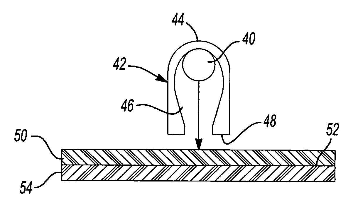
[0042] Referring now to FIG. 4, an apparatus and a method for welding a first plastic part 10 to a second plastic part 12 using a first incoherent infrared light source 14 and a second incoherent infrared light source 16 is provided according to the principles of the present teachings. Specifically, first incoherent infrared light source 14 and second incoherent infrared light source 16 are each mounted to and carried by a support structure 18. First incoherent infrared light source 14 is disposed within a first negative waveguide assembly 20. First negative waveguide assembly 20 comprises a reflector portion 22 and a negative waveguide portion 24. In some embodiments, negative waveguide portion 24 is formed integrally with reflector portion 22 to form a single, unitary assembly. In some embodiments, first incoherent ...


PUM

PropertyMeasurementUnit
Angleaaaaaaaaaa
Widthaaaaaaaaaa
Energyaaaaaaaaaa

Abstract

An assembly for producing a weld coupling a first part of a workpiece to a second part of the workpiece. The assembly comprises a first incoherent light source that generates incoherent light energy and a first negative waveguide having an input end and an output end, the incoherent light energy from the first incoherent light source and that reflected by the first reflector entering the first negative waveguide at the input end, passing through the first negative waveguide and exiting the first negative waveguide at the output end. The first negative waveguide having a non-conical longitudinal cross section producing a non-circular weld zone

Description

CROSS-REFERENCE TO RELATED APPLICATIONS [0001] This application is a continuation-in-part of U.S. patent application Ser. No. 11 / 216,711 filed on Aug. 31, 2005. The disclosure of the above application is incorporated herein by reference.FIELD OF THE INVENTION [0002] The present invention relates generally to plastics welding and, more particularly, relates to waveguides for use with an incoherent infrared light source for plastics welding. BACKGROUND AND SUMMARY OF THE INVENTION [0003] Currently, the art of welding plastic or resinous parts incorporates a variety of techniques including ultrasonic welding, heat welding, and, most recently, Through Transmission Infrared (TTIr) welding. [0004] TTIR welding employs infrared light passed through a first plastic part and into a second plastic part. TTIR welding can use either infrared laser light or incoherent infrared light in the current art. Infrared laser light in the current art can be directed by fiber optics, waveguides, or light ...

Claims


Application Information

Patent Timeline
IPC IPC(8): F21V7/00G02B17/00
CPCB29C65/14B29C65/1496B29C65/1432B29C65/1435B29C65/1467B29C65/1487B29C65/16B29C65/1612B29C66/24B29C66/244B29C66/301B29C66/80G02B6/0008B29C65/1412B29C66/54B29C65/00B29C66/83221B29C66/73921B29C66/81263B29K2995/0027B29C66/1122
Inventor CALDWELL, SCOTTNELSON, KENNETHHERSHEY, DANIEL
Owner BRANSON ULTRASONIC CORP
Why Eureka
Try Eureka