Magnetoresistive effect element, magnetic head, magnetic storage device and magnetic memory device

a technology of magnetoresistive effect and magnetic head, which is applied in the direction of magnetic bodies, instruments, transportation and packaging, etc., can solve the problems of reducing the output of a magnetoresistive element. , to achieve the effect of high output of a magnetoresistive effect element, good sensitivity to a signal magnetic field, and extremely high output of a magn

Inactive Publication Date: 2007-03-01
FUJITSU LTD
View PDF19 Cites 31 Cited by
  • Summary
  • Abstract
  • Description
  • Claims
  • Application Information

AI Technical Summary

Benefits of technology

[0012] It is a general object of the present invention to provide an improved and useful magnetoresistive element in which the above-mentioned problems are eliminated.
[0013] A more specific object of the present invention is to provide a magnetoresistive element having a high output and also having a good sensitivity in detection of a magnetic field, and a magnetic head and a magnetic storage device having such a magnetoresistive element.

Problems solved by technology

In such a case of reducing the element thickness, if the CIP structure is used, a current density of the sense current is large, that may cause degradation in a performance due to migration in materials forming a spin valve film.
Thus, a substantial amount of change in magnetic resistance is decreased, which results in reduction of an output of a magnetoresistive element.
Additionally, if a coercive force is too large, magnetization of a free magnetization layer by a signal magnetic field hardly rotates, which may result in that an output is hardly obtained.

Method used


Image

  • Magnetoresistive effect element, magnetic head, magnetic storage device and magnetic memory device
  • Magnetoresistive effect element, magnetic head, magnetic storage device and magnetic memory device
  • Magnetoresistive effect element, magnetic head, magnetic storage device and magnetic memory device

Examples


first embodiment

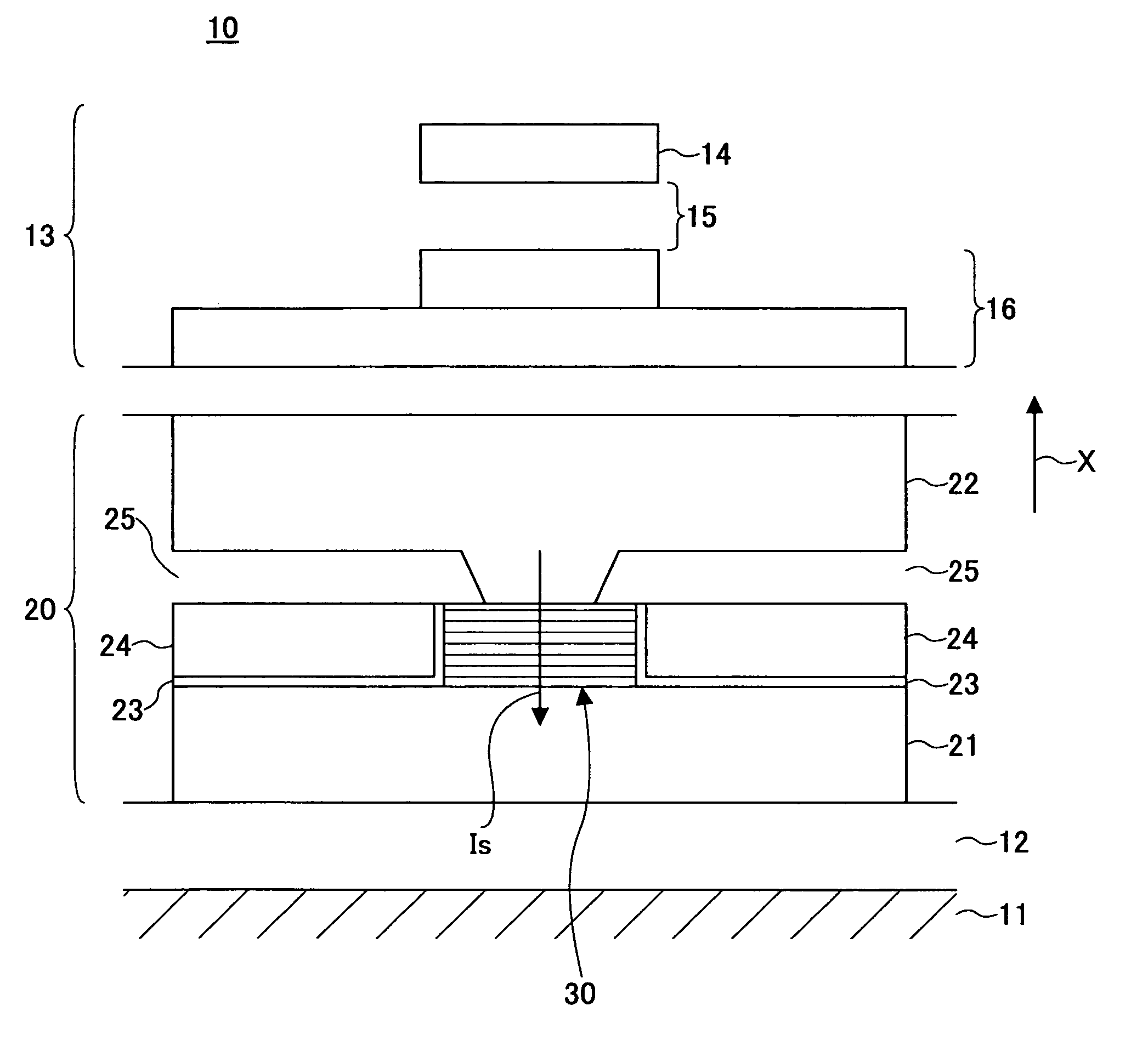
[0044] A description will now be given of a compound type magnetic head having a magnetoresistive effect element according to a first embodiment of the present invention and an induction type recording element. FIG. 1 is an illustration showing a part the compound type magnetic head. In FIG. 1, an arrow X indicates a direction of movement of a magnetic recording medium facing the magnetoresistive effect element.

[0045] With reference to FIG. 1, the compound type magnetic head 10 comprises a flat ceramic substrate 11 formed of Al2O3—TiC and serving as a head slider, the magnetoresistive effect element 20 formed on the ceramic substrate 11, and the induction type recording element 13 formed on the magnetoresistive effect element 20.

[0046] The induction type recording element 13 comprises: an upper magnetic pole 14 facing a magnetic recording medium and having a width corresponding to a track width of the magnetic recording medium; a recording gap layer 15; a lower magnetic pole 16 op...

example 1

PRACTICAL EXAMPLE 1

[0098] In the practical example 1, the magnetoresistive effect element having the structure of the GMR film of the second example shown in FIG. 3 was fabricated.

[0099]FIG. 7 is an illustration showing compositions of the free magnetization layer and the lower and upper second fixed magnetization layers, a coercive force and an amount of change in magnetic resistance ΔRA in the practical example 1.

[0100] With reference to the FIG. 7, samples of No. 1 through No. 27 are changed in their composition of CoFeAl used for the lower second fixed magnetization layer, the free magnetization layer and the upper second fixed magnetization layer. The samples of the practical example 1 were fabricated as follows.

[0101] A layered film of Cu (250 nm) / NiFe (50 nm) is formed as a lower electrode on a silicon substrate on which a thermal oxidation film is formed. Then, each layer of the foundation layer to the protection layer of the lower layered product, which has the following...

example 2

PRACTICAL EXAMPLE 2

[0126] In a practical example 2, the magnetoresistive effect element which has the composition of the GMR film of the fifth example according to the first embodiment shown in FIG. 6 was fabricated. In the practical example, the composition of the free magnetization layer was fixed to Co50Fe20Al30, and the composition of CoFeAl of the lower second fixed magnetization layer and the upper second fixed magnetization layer was changed so as to form the magnetoresistive effect element of the samples No. 31 through No. 37. The composition range of the samples No. 31 through No. 37 is a range CHIDC in the diagram of FIG. 8. The range CHIDC is defined by straight lines connecting points C, H, I, D and C sequentially in that order, where the point H is (40, 30, 30) and the point I is (50, 30, 20), where the coordinates of each composite is expressed by (Co content, Fe content and Al content) in FIG. 8. It should be noted that the lower second fixed magnetization layer and t...


PUM

PropertyMeasurementUnit
thicknessaaaaaaaaaa
thicknessaaaaaaaaaa
thicknessaaaaaaaaaa

Abstract

A magnetoresistive effect element of a CPP type includes a fixed magnetization layer, a non-magnetic layer and a free magnetization layer formed of CoFeAl. The CoFeAl has a composition falling within a range defined by straight lines connecting points A, B, C, D, E, F and A, in that order, in a ternary composition diagram. The point A is (55, 10, 35), the point B is (50, 15, 35), the point C is (50, 20, 30), the point D is (55, 25, 20), the point E is (60, 25, 15), and the point F is (70, 15, 15), where coordinates of the composition of each point is represented by (Co content, Fe content, Al content). Each content is expressed by atomic percent.

Description

BACKGROUND OF THE INVENTION [0001] 1. Field of the Invention [0002] The present invention relates to magnetoresistive effect elements for reproducing information in magnetic storage device and, more particularly, to a magnetoresistive effect element having a structure of a CPP (Current-Perpendicular-to-Plane) in which a sense current flows in a direction of lamination of a film stack constituting the magnetoresistive effect element. [0003] 2. Description of the Related Art [0004] In recent years, a magnetoresistive effect element is used for a magnetic head of a magnetic storage, as a reproducing element for reproducing information recorded on a magnetic recording medium. The magnetoresistive effect element reproduces information recorded on a magnetic-recording medium using a magnetoresistive effect, which converts a change in a direction of a signal magnetic field leaking from a magnetic recording medium into a change in electric resistance. [0005] With progress in high recording ...

Claims


Application Information

Patent Timeline
Patent Type & Authority Applications(United States)
IPC IPC(8): B32B3/02
CPCB82Y25/00G01R33/093G11B5/3906H01F10/16Y10T428/21H01F10/3263H01F10/3272H01L27/228H01L43/10H01F10/3254H10B61/22H10N50/85H10N50/10
Inventor JOGO, ARATAOSHIMA, HIROTAKANAGASAKA, KEIICHI
Owner FUJITSU LTD
Why Eureka
Try Eureka