Radio-frequency tuner with differential converter

a technology of differential converter and radio frequency tuner, which is applied in diversity/multi-antenna system, polarisation/directional diversity, and resonant circuits using central processing units. it can solve problems such as difficult design, compromise receiver performance, and difficulty in tuning across multiple sub-bands of radio-frequency spectrum, so as to reduce headroom and noise reduction, the effect of greater flexibility

Inactive Publication Date: 2007-03-01
CSR TECH INC
View PDF15 Cites 16 Cited by
  • Summary
  • Abstract
  • Description
  • Claims
  • Application Information

AI Technical Summary

Benefits of technology

[0009] Important technical advantages of certain embodiments of the present invention include power saving benefits, space-saving packaging, and greater operational flexibility. In particular, certain embodiments may be capable of operating with reduced headroom. Additionally, certain embodiments may be able to isolate internal signals from one another in an improved manner so as to provide greater noise-reduction. Other technical advantages of the present invention will be readily apparent to one skilled in the art from the following figures, descriptions, and claims. Moreover, while specific advantages have been enumerated above, various embodiments may include all, some, or none of the enumerated advantages.

Problems solved by technology

This flexibility may provide significant design challenges when combined with the space and power restrictions associated with mobile devices.
In particular, receivers that can tune across multiple sub-bands of the radio-frequency spectrum, including sub-bands of different sizes, can be difficult to design.
Designing a receiver to accept signals within multiple sub-bands of varying sizes may compromise the receiver's performance when receiving signals in some or all of the sub-bands.
Furthermore, the power limitations faced by mobile devices result in headroom requirements for such devices that create additional design challenges.

Method used


Image

  • Radio-frequency tuner with differential converter
  • Radio-frequency tuner with differential converter
  • Radio-frequency tuner with differential converter

Examples


Embodiment Construction

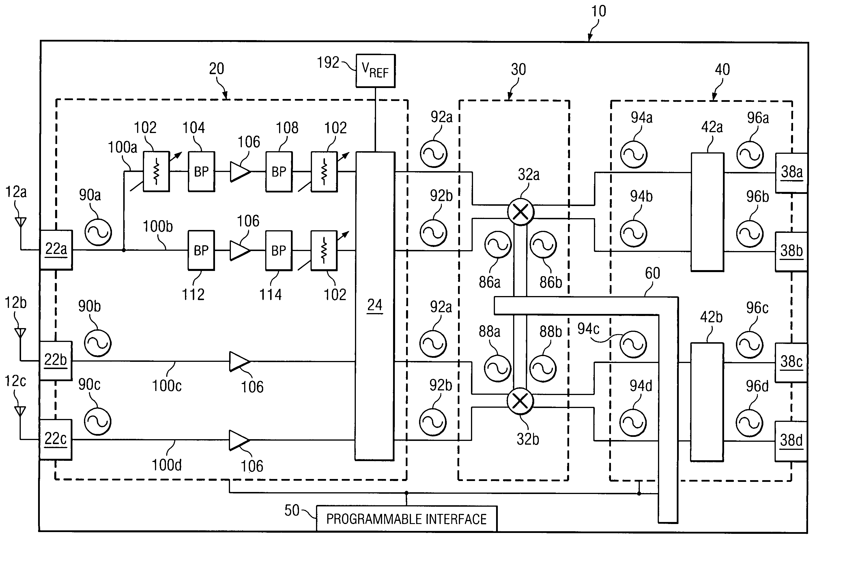
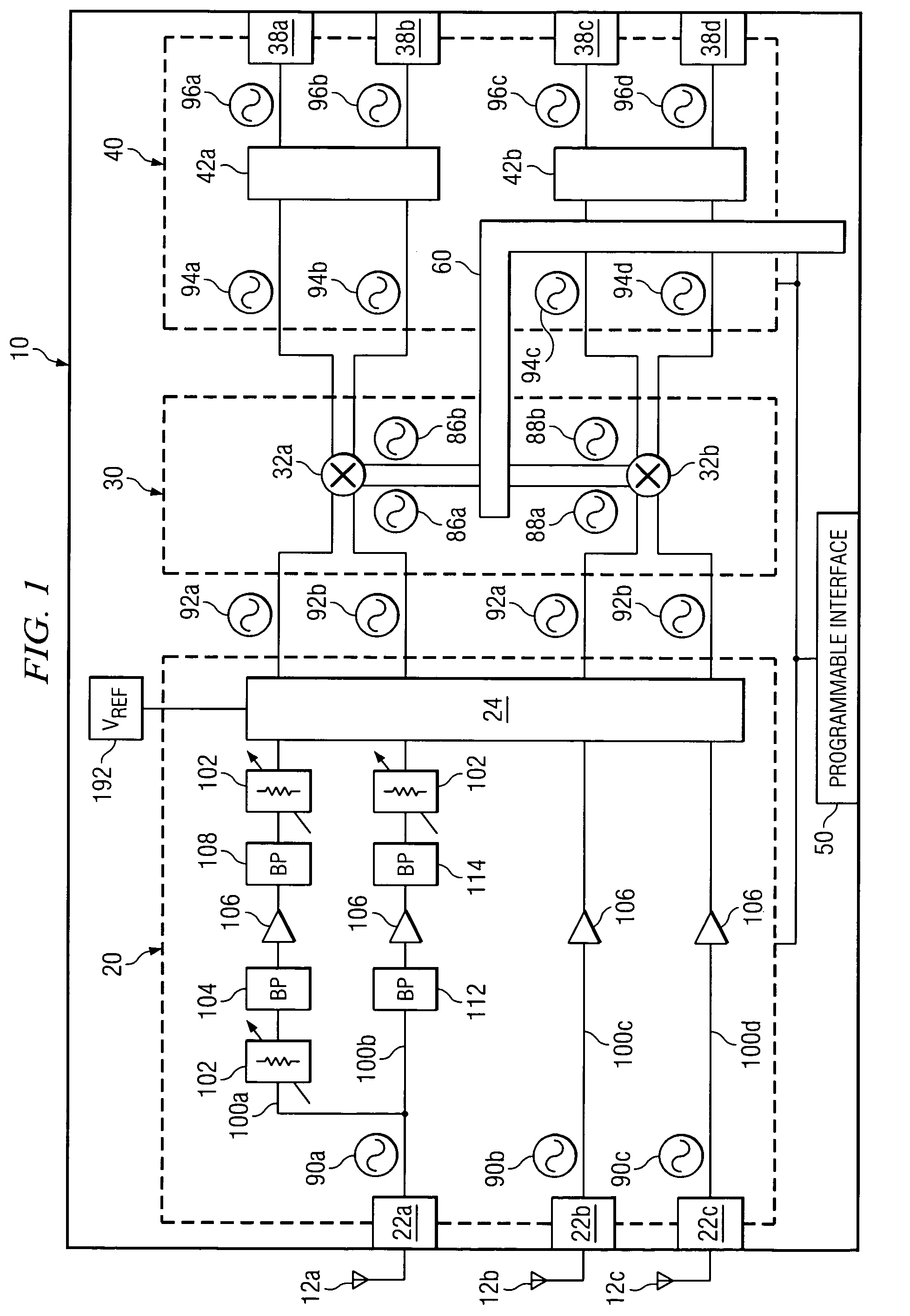
[0014]FIG. 1 is a block diagram illustrating functional components of a particular embodiment of a tuner 10 capable of tuning radio-frequency signals received over multiple sub-bands of the radio-frequency spectrum. As shown in FIG. 1, tuner 10 includes a radio-frequency (RF) stage 20, a mixing stage 30, a baseband stage 40, a programmable interface 50, and a frequency generation circuit 60. Additionally, tuner 10 couples to a plurality of antennas 12 through which tuner 10 receives input signals 90. Tuner 10 isolates and outputs information within a particular range of frequencies, or “channel”, selected by a user or another component coupled to tuner 10. In particular embodiments, tuner 10 is capable of tuning input signals 90 received within different sub-bands of varying size without substantial deterioration in performance. Additionally, in particular embodiments, based on the configuration of the various elements of tuner 10, tuner 10 may be capable of operating with low headr...


PUM


Abstract

A system for tuning a radio-frequency signal includes a first input path, a second input path, a common reference generator, a selector, a mixer, and a filter. The first input path and the second input path propagate a first single-ended input signal and a second single-ended input signal, respectively, to the selector. The selector converts the first single-ended input signal and the second single-ended input signal into a first differential input signal and a second differential input signal, respectively, using a reference signal generated by the common reference generator. The selector selectively couples one of the first and the second input path to an input of the mixer. The mixer downconverts a selected on of the differential input signals received from the selector. The filter attenuates a portion of the downconverted input signal outside a passband associated with the filter.

Description

TECHNICAL FIELD OF THE INVENTION [0001] This invention relates in general to radio-frequency signal tuners and, more particularly, to a multi-band digital broadcast tuner. BACKGROUND OF THE INVENTION [0002] Recent developments in communication technology have led to the introduction of mobile digital communication devices that provide several different types of service. As a result, modern communication devices may be faced with the task of receiving and processing a variety of different types of signals. This flexibility may provide significant design challenges when combined with the space and power restrictions associated with mobile devices. [0003] In particular, receivers that can tune across multiple sub-bands of the radio-frequency spectrum, including sub-bands of different sizes, can be difficult to design. Designing a receiver to accept signals within multiple sub-bands of varying sizes may compromise the receiver's performance when receiving signals in some or all of the s...

Claims


Application Information

Patent Timeline
Patent Type & Authority Applications(United States)
IPC IPC(8): H04B1/18
CPCH04B1/28H03J1/0008
Inventor WOMAC, MICHAEL D.
Owner CSR TECH INC
Why Eureka
Try Eureka