Spinal implants and methods of providing dynamic stability to the spine

Inactive Publication Date: 2007-03-01
MAGELLAN SPINE TECH
View PDF83 Cites 18 Cited by
  • Summary
  • Abstract
  • Description
  • Claims
  • Application Information

AI Technical Summary

Problems solved by technology

These spinal implants and methods are, however, susceptible to modifications a

Method used


Image

  • Spinal implants and methods of providing dynamic stability to the spine
  • Spinal implants and methods of providing dynamic stability to the spine
  • Spinal implants and methods of providing dynamic stability to the spine

Examples


Embodiment Construction

,” one will understand how the features of the preferred embodiments provide advantages, which include, inter alia, the capability to repair annular defects and stabilize adjacent motion segments of the spine without substantially diminishing the range of motion of the spine, simplicity of structure and implantation, and a low likelihood that the implant will migrate from the implantation site.

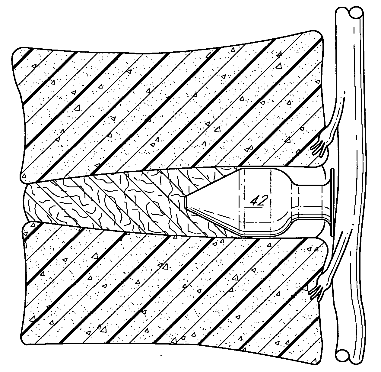
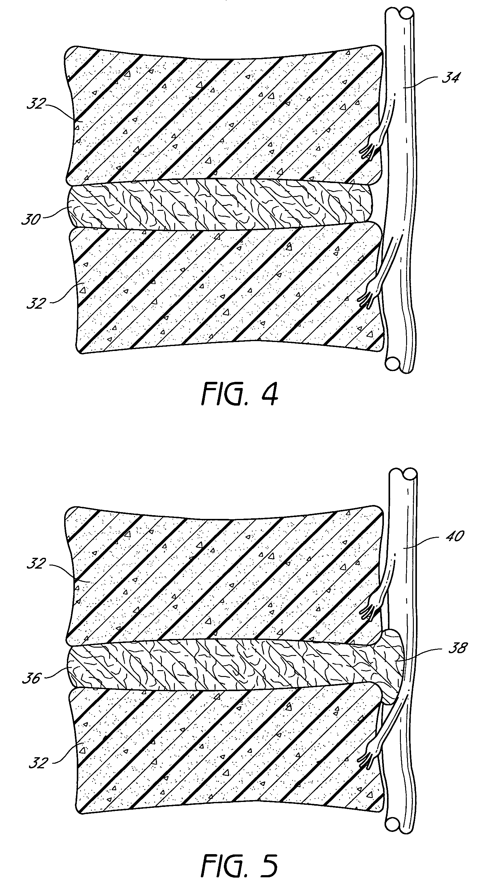
[0016] One embodiment of the present spinal implants and methods of providing dynamic stability to the spine comprises a spinal implant adapted to be implanted in an intervertebral disc located between a first vertebral disc and a second vertebral disc to repair an annular defect in the intervertebral disc, and to provide dynamic stability to a motion segment of a spine in the vicinity of the intervertebral disc. The implant comprises a head portion including at least a first head segment and a second head segment. Each of the first and second head segments has a length greater than zero as me...


PUM


Abstract

The present application discloses a plurality of spinal implants and methods for repairing annular defects in intervertebral discs and for providing dynamic stability to the motion segment of the spine in the vicinity of the repaired disc. Each of the implants comprises a head portion and a tail portion. In the illustrated embodiments, the head portion of each implant is enlarged relative to the tail portion. Each of the head portions and tail portions is adapted to support adjacent vertebrae and resist collapse of the intervertebral disc. A tapered portion of each implant engages end plates of the adjacent vertebrae to resist forces tending to push the implant out of the intervertebral space. The tail portion of each implant includes a tail flange (which in some embodiments is of similar diameter to the head portion) that abuts extradiscal lips of the adjacent vertebrae and resists forces tending to push the implant deeper into the intervertebral space.

Description

CROSS-REFERENCE TO RELATED APPLICATION [0001] This application claims priority to provisional application Ser. No. 60 / 711,714, filed on Aug. 26, 2005, the entire contents of which are hereby expressly incorporated by reference.BACKGROUND OF THE INVENTION [0002] 1. Field of the Invention [0003] The present invention relates to devices and methods for repairing annular defects in intervertebral discs and for providing dynamic stability to the motion segment of the spine in the vicinity of the repaired disc. [0004] 2. Description of the Related Art [0005] The vertebral spine is the axis of the skeleton upon which all of the body parts “hang.” In humans, the normal spine has seven cervical, twelve thoracic and five lumbar segments. The lumbar segments sit upon a sacrum, which then attaches to a pelvis, in turn supported by hip and leg bones. The bony vertebral bodies of the spine are separated by intervertebral discs, which act as joints, but allow known degrees of flexion, extension, l...

Claims


Application Information

Patent Timeline
IPC IPC(8): A61F2/44A61B17/16
CPCA61B17/1615A61F2310/00011A61B17/70A61B2017/00261A61B2019/461A61B2019/462A61F2/442A61F2/4611A61F2/4684A61F2002/2835A61F2002/30112A61F2002/30113A61F2002/30242A61F2002/30383A61F2002/30405A61F2002/30448A61F2002/30462A61F2002/30481A61F2002/30565A61F2002/30574A61F2002/30604A61F2002/30616A61F2002/30787A61F2002/3085A61F2002/30892A61F2002/4435A61F2002/4475A61F2002/4629A61F2002/4677A61F2220/0025A61F2220/005A61F2220/0075A61F2230/0004A61F2230/0006A61F2230/0071A61B17/1671A61B2090/061A61B2090/062A61F2002/30593
Inventor CONNER, E. SCOTT
Owner MAGELLAN SPINE TECH
Why Eureka
Try Eureka