NC Machine Tool

a machine tool and tool technology, applied in the field of nc machine tools, can solve the problems of reducing productivity and taking cost to construct a structure, and achieve the effect of preventing a tool exchange error

Inactive Publication Date: 2007-03-01
YAMAZAKI MAZAK KK
View PDF5 Cites 22 Cited by
  • Summary
  • Abstract
  • Description
  • Claims
  • Application Information

AI Technical Summary

Benefits of technology

[0004] An objective of the present invention is to provide an NC machine tool capable of preventing a tool exchange error by drawing an attention of the operator on the basis of internal data of a machine tool.

Problems solved by technology

However, the technique serves to reduce damage caused by interference of the tool with the machine, not to prevent occurrence of a tool exchange error.
For this reason, even when damage due to interference of the tool with the machine is suppressed, both of the tool and the machine can be damaged or operation of the machine tool can be stopped, resulting in a decrease in productivity.
However the technique has the disadvantage that it takes cost to construct a structure for recognizing the shape of the tool and determining the tool exchange error.

Method used


Image

  • NC Machine Tool
  • NC Machine Tool
  • NC Machine Tool

Examples


Embodiment Construction

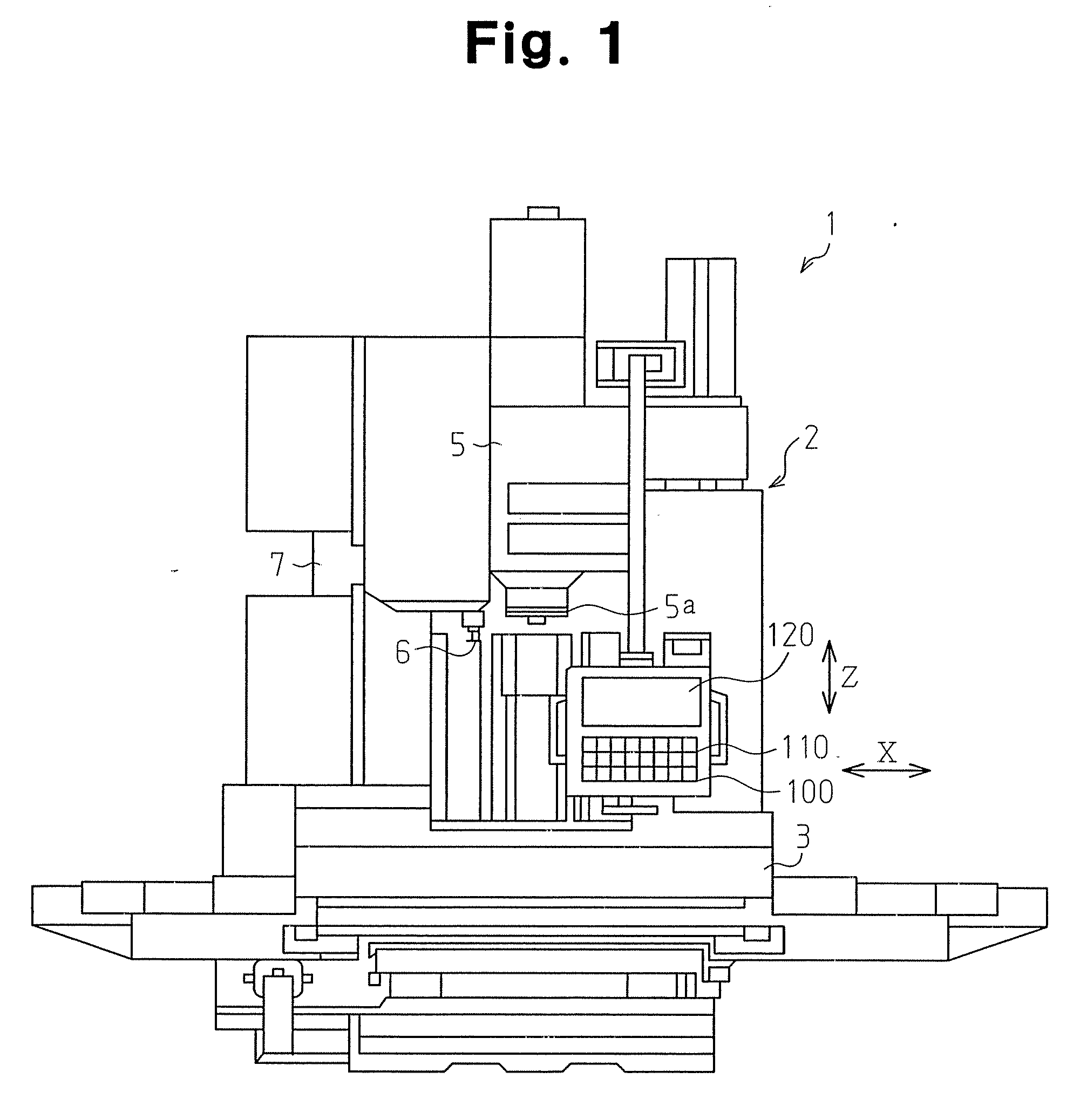
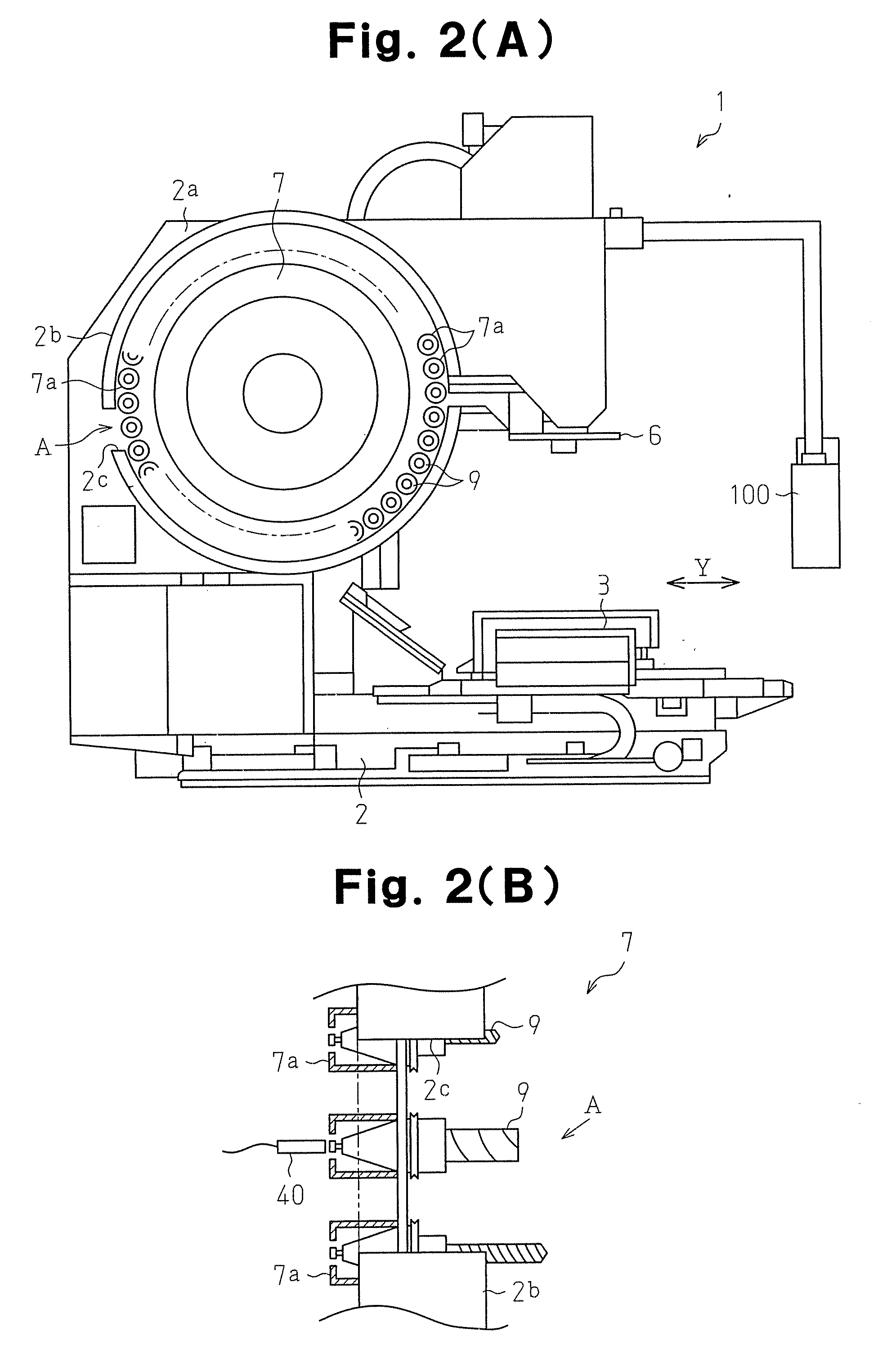
[0017] With reference to FIGS. 1 to 10, an embodiment of an NC machine tool of the present invention embodied by a vertical machining center will be described below.

[0018] As shown in FIGS. 1, 2(A), and 2(B), a machining center 1 has a main unit 2. A table 3 is supported by the main unit 2 so as to be movable in a horizontal direction (X-axis direction, Y-axis direction). A column 2a of the main unit 2 is provided with a spindle head 5. The spindle head 5 is disposed above the table 3. The spindle head 5 is supported so as to be movable in a vertical direction (Z-axis direction) with respect to the table 3.

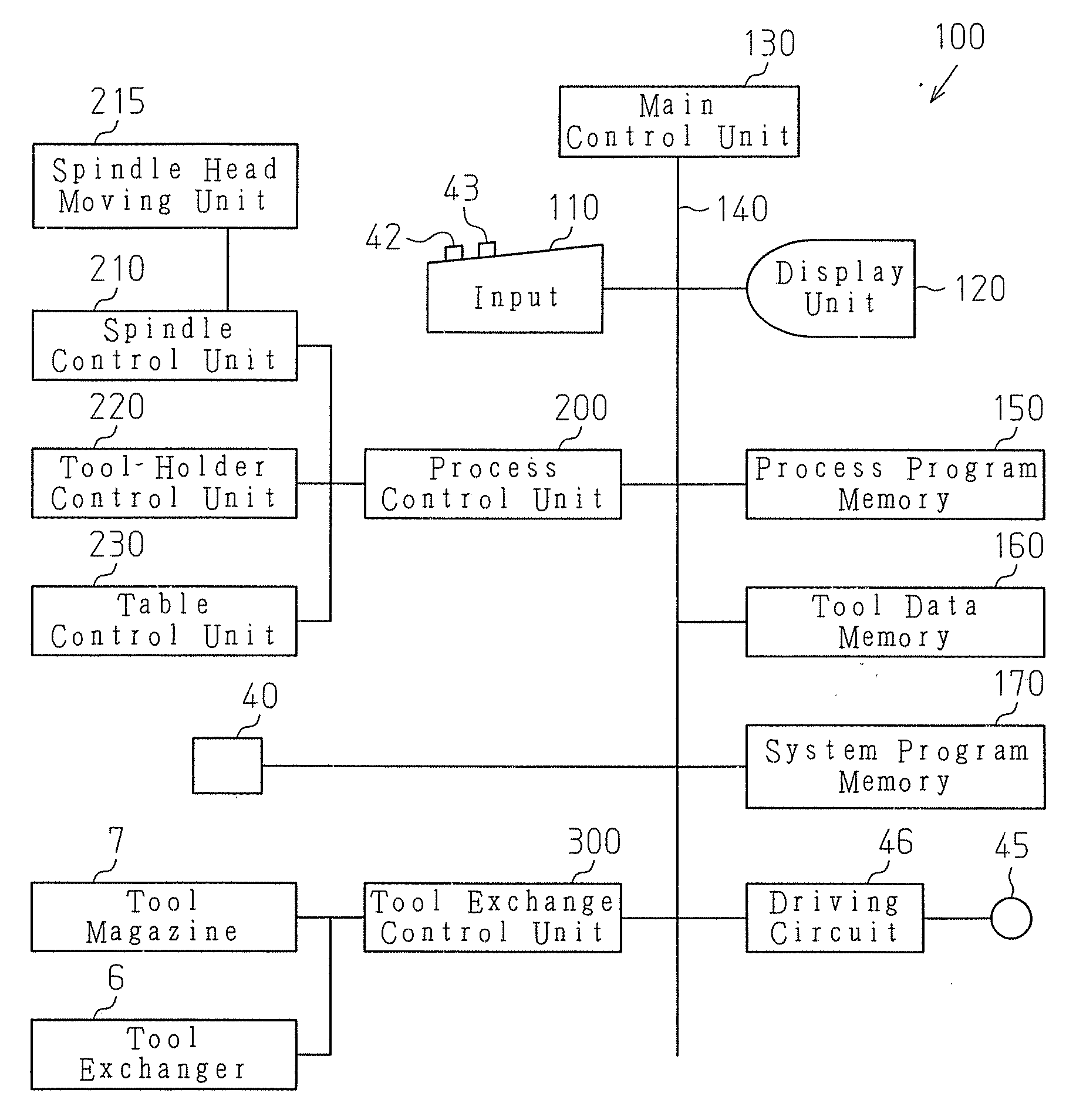
[0019] The table 3 and the spindle head 5 are held in the machining center 1 so as to be relatively movable along three axes (X, Y, Z), all perpendicular to one another. In the machining center 1, the amount of movement of the table 3 and the spindle head 5 is controlled by an NC device 100 and a work set on the table 3 is machined by use of a tool K attached to the spindle head...


PUM


Abstract

The NC device of the machining center has the data memory for storing exchange history and data concerning a tool therein when the tool has been manually exchanged. When the data concerning the tool is updated, the data memory also stores update history. The main control unit determines whether the tool is changed on the basis of at least either of the exchange history and the update history. On the basis of a determination result, the main control unit controls the spindle head moving unit to stop the tool as well as allows a caution about the tool to be displayed on the display unit.

Description

BACKGROUND OF THE INVENTION [0001] The present invention relates to an NC machine tool, in particular, an NC machine tool capable of preventing a tool exchange error by the operator. [0002] Conventionally, there have been NC machine tools having a function of automatically exchanging tools. For example, Japanese Laid-Open Patent Publication No. 11-33867 discloses a technique of detecting change of a machining program, tool exchange, change of data correction amount by sensors, in preparation for the case where the tool interferes with a machine, and decreasing rapid transverse speed of the tool to perform automatic operation of a machine tool. However, the technique serves to reduce damage caused by interference of the tool with the machine, not to prevent occurrence of a tool exchange error. For this reason, even when damage due to interference of the tool with the machine is suppressed, both of the tool and the machine can be damaged or operation of the machine tool can be stopped...

Claims


Application Information

Patent Timeline
Patent Type & Authority Applications(United States)
IPC IPC(8): G06F19/00B23Q3/155G05B19/18
CPCG05B19/40938G05B2219/50245G05B2219/34393Y02P90/02
Inventor ITOH, HIROSHISUMIDA, YASUHARUKIKATA, KAZUHIRO
Owner YAMAZAKI MAZAK KK
Why Eureka
Try Eureka