

Structure of pattern pressing roller
- Summary
- Abstract
- Description
- Claims
- Application Information
AI Technical Summary
Benefits of technology
Problems solved by technology
Method used
Image

Examples
Embodiment Construction
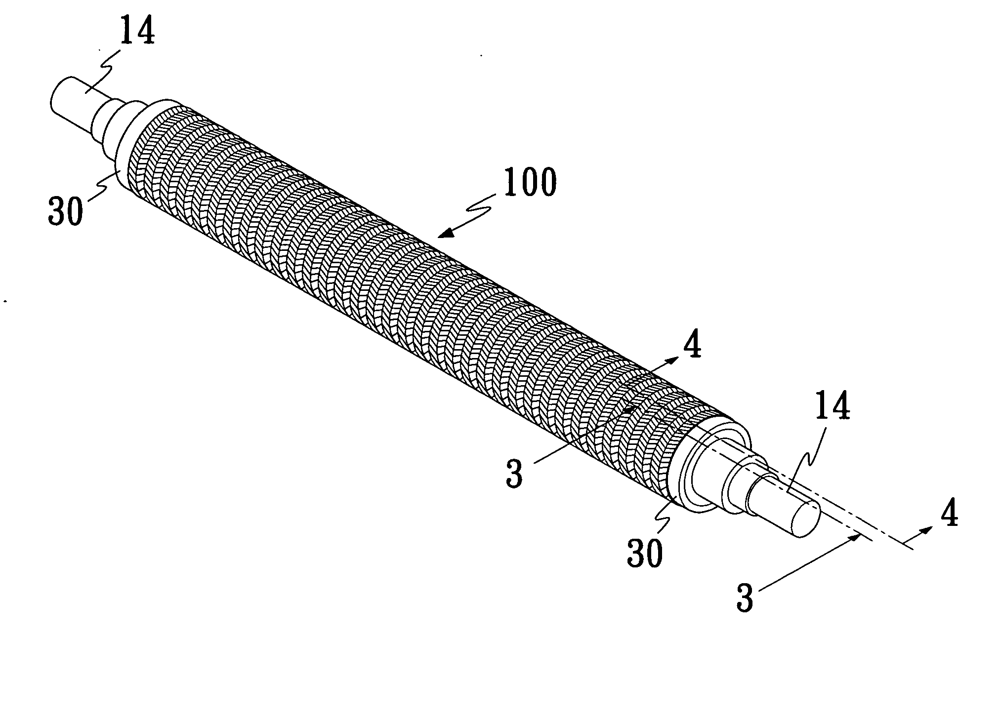
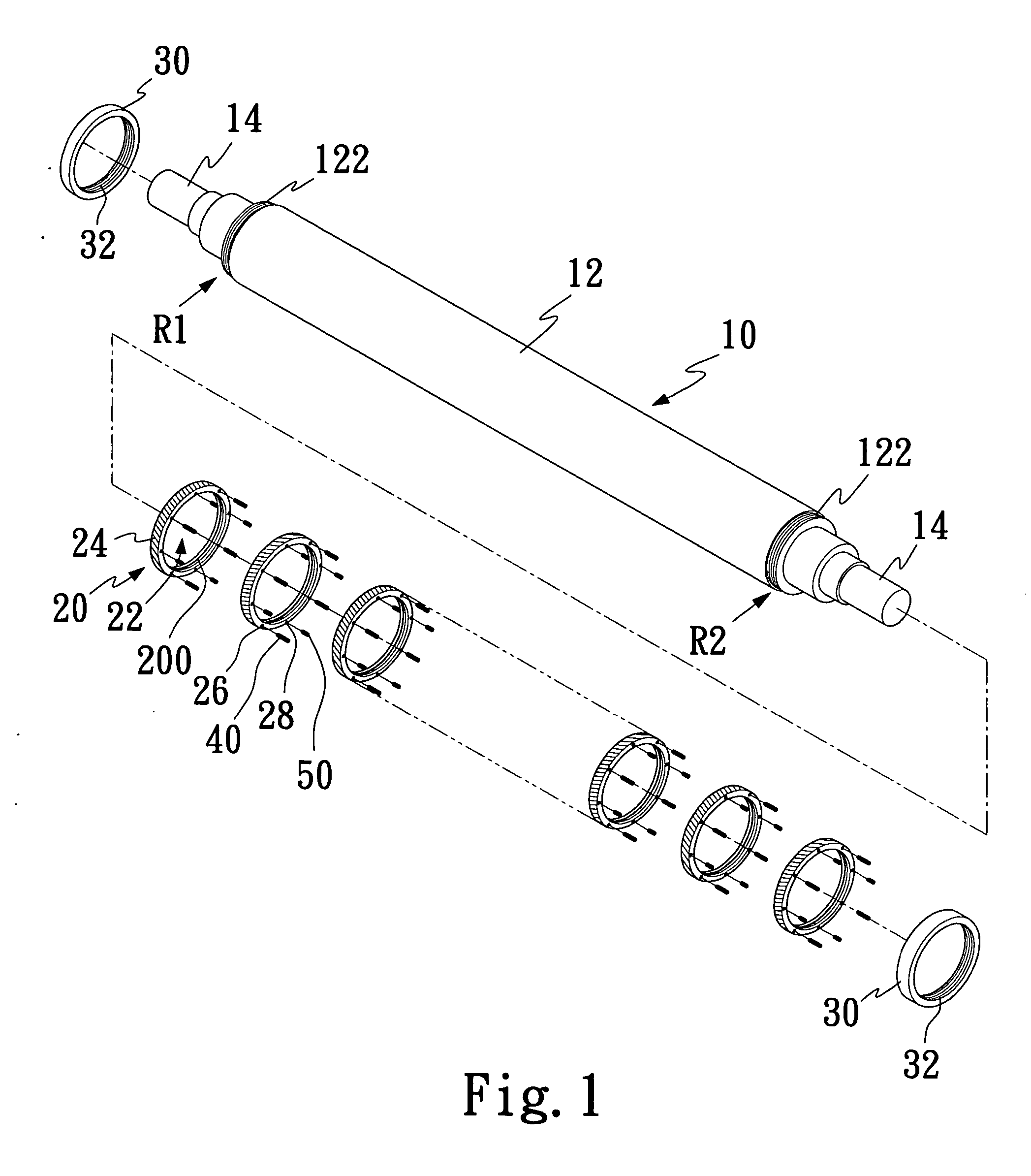
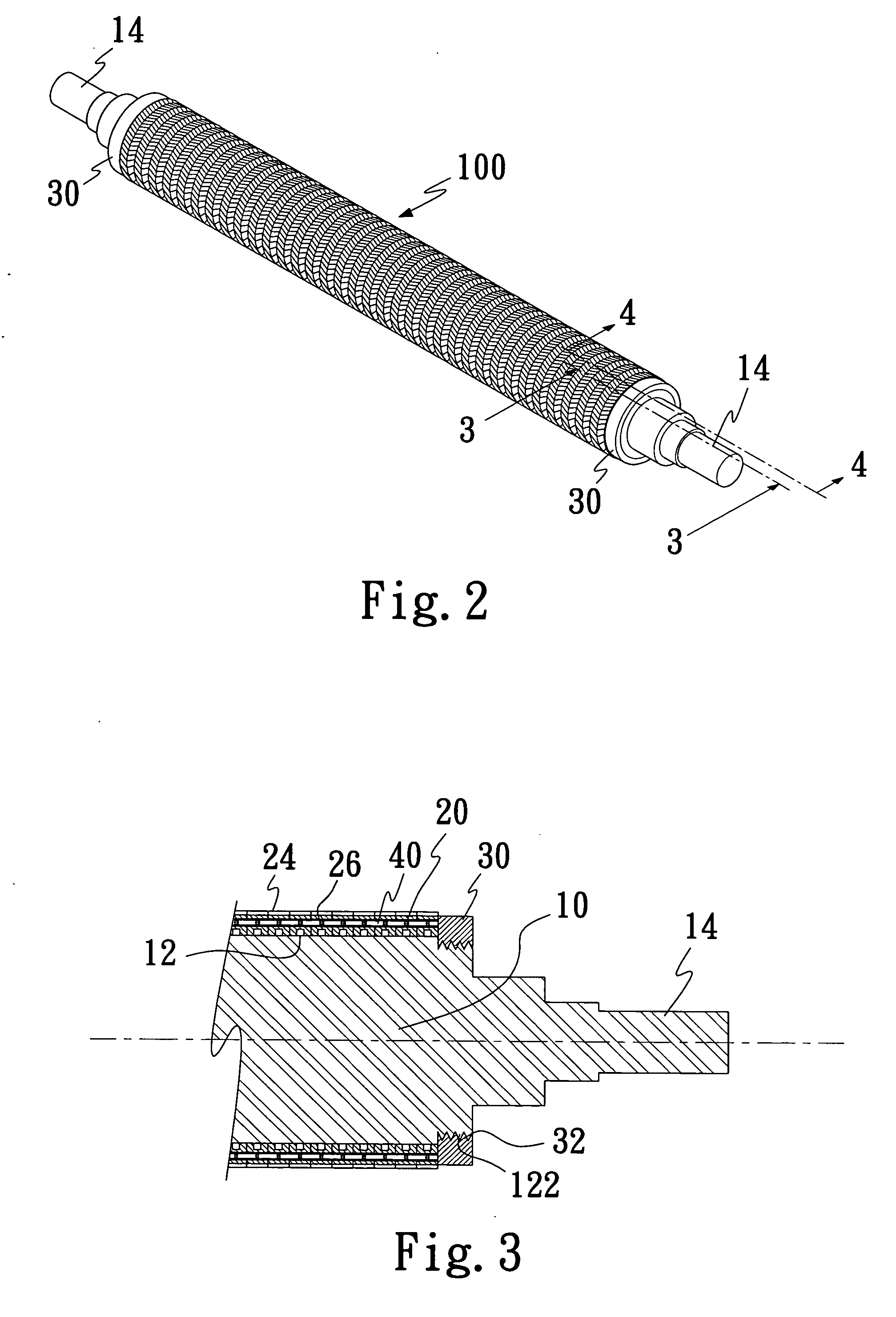
[0021]FIG. 1 shows a 3-D assembled view of a structure of pattern pressing roller in accordance with a preferred embodiment of the present invention. FIG. 2 illustrates an 3-D view of an assembled structure of pattern pressing roller in accordance with a preferred embodiment of the present invention. The pattern pressing roller of the present invention comprises a shaft 10, a plurality of pattern pressing loops 20 and two secured rings 30, wherein the pattern pressing loops 20 can be inserted onto a middle portion 12 of the shaft 10. Once all the patter pressing loops 20 are located within the shaft 10, the two secured rings 30 are utilized to secure the pattern pressing loops 20 by inserting into both ends of the shaft 10 respectively. The two secured rings 30 are utilized to compress those patter pressing loops 20 tightly against each other in order to prevent any one of them coming off from the shaft 10.
[0022] The shaft 10 can be made of various kinds of carbon steel materials o...
PUM
 Abstract
Description
Claims
Application Information