Self-locking self-bonding regid coupling

a self-locking, regid coupling technology, applied in the direction of fluid pressure sealing joints, hose connections, mechanical equipment, etc., can solve the problems of looseness or flexibility of the connection between the first and second conduit members, and achieve the effect of enhancing electrical conductivity, minimal or no static buildup, and enduring electrical conductivity

Active Publication Date: 2007-03-08
EATON INTELLIGENT POWER LTD
View PDF14 Cites 27 Cited by
  • Summary
  • Abstract
  • Description
  • Claims
  • Application Information

AI Technical Summary

Benefits of technology

[0015] The complementary peripheral facing surfaces in the preferred embodiment include at least one notch or relief formed on the lock nut group, and a corresponding at least one projection or tab formed on a peripheral surface of the threaded flange The predetermined amount of rotation of the lock nut group with respect to the standard flange results in positive engagement of the tab(s) with corresponding notch(es).
[0020] The coupling of the present invention also maintains outstanding electrical conductivity through the entire fitting assembly to ensure that there is minimal or no static buildup across the connection between the conduit members. The use of a single o-ring member which is bypassed by metal to metal contact of numerous components of the coupling assembly ensures that there is minimal isolation of parts in the first and second conduit members. Additionally, electrical conductivity can be further enhanced by coating various elements of the coupling assembly with conductive coatings. Conductive coatings that may be used include electroless nickel or nickel Teflon coatings. One or more of the parts or elements, as necessary, can be provided with the conductive coatings. Accordingly, the coupling assembly of the present invention requires no bonding springs within the conduit members, nor does the coupling require any electrical jumpers that are normally mounted to the coupling assembly in order to ensure electrical continuity.

Problems solved by technology

Looseness or flexibility of the connection between the first and second conduit members is limited by a number of factors.

Method used


Image

  • Self-locking self-bonding regid coupling
  • Self-locking self-bonding regid coupling
  • Self-locking self-bonding regid coupling

Examples


Embodiment Construction

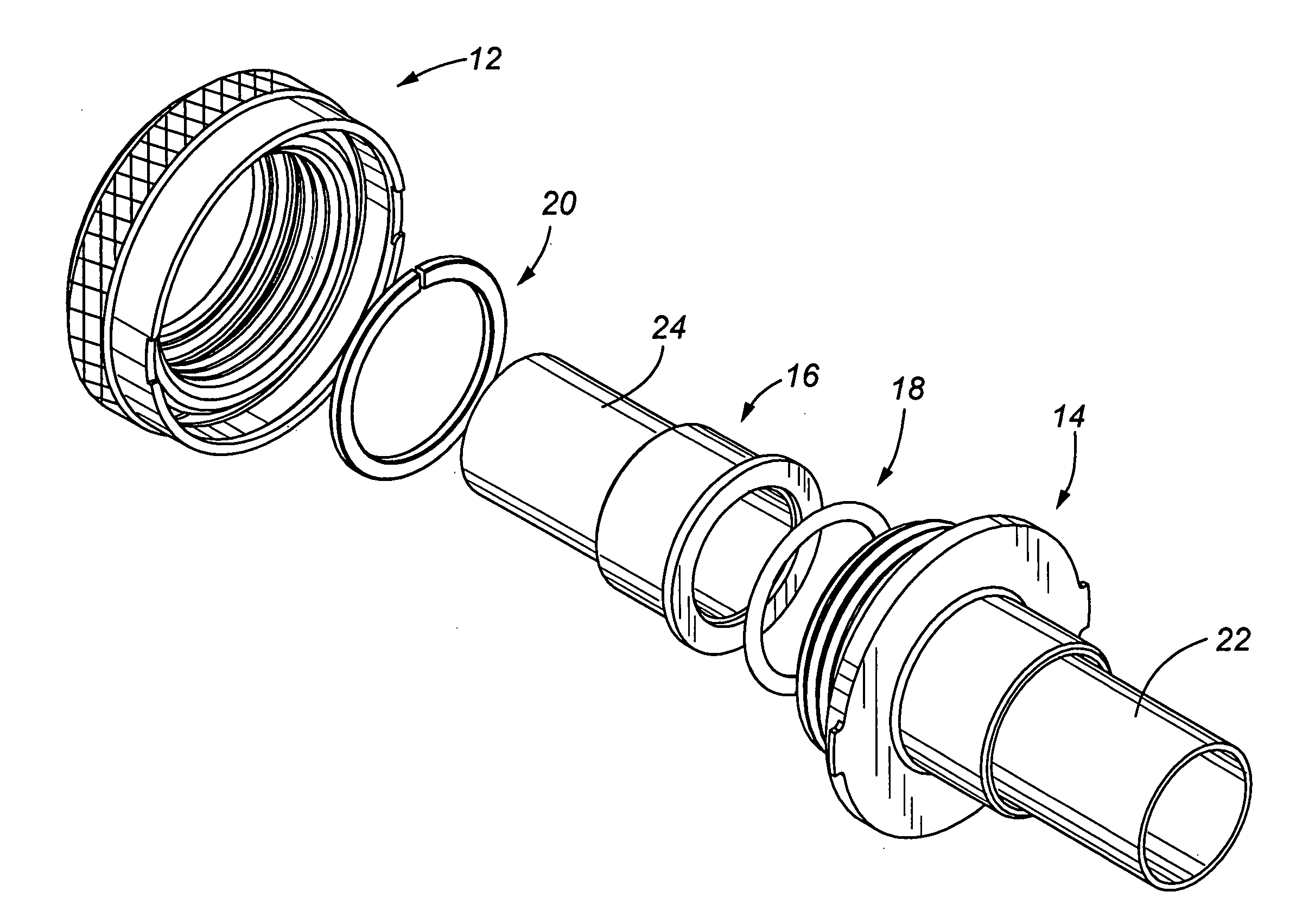
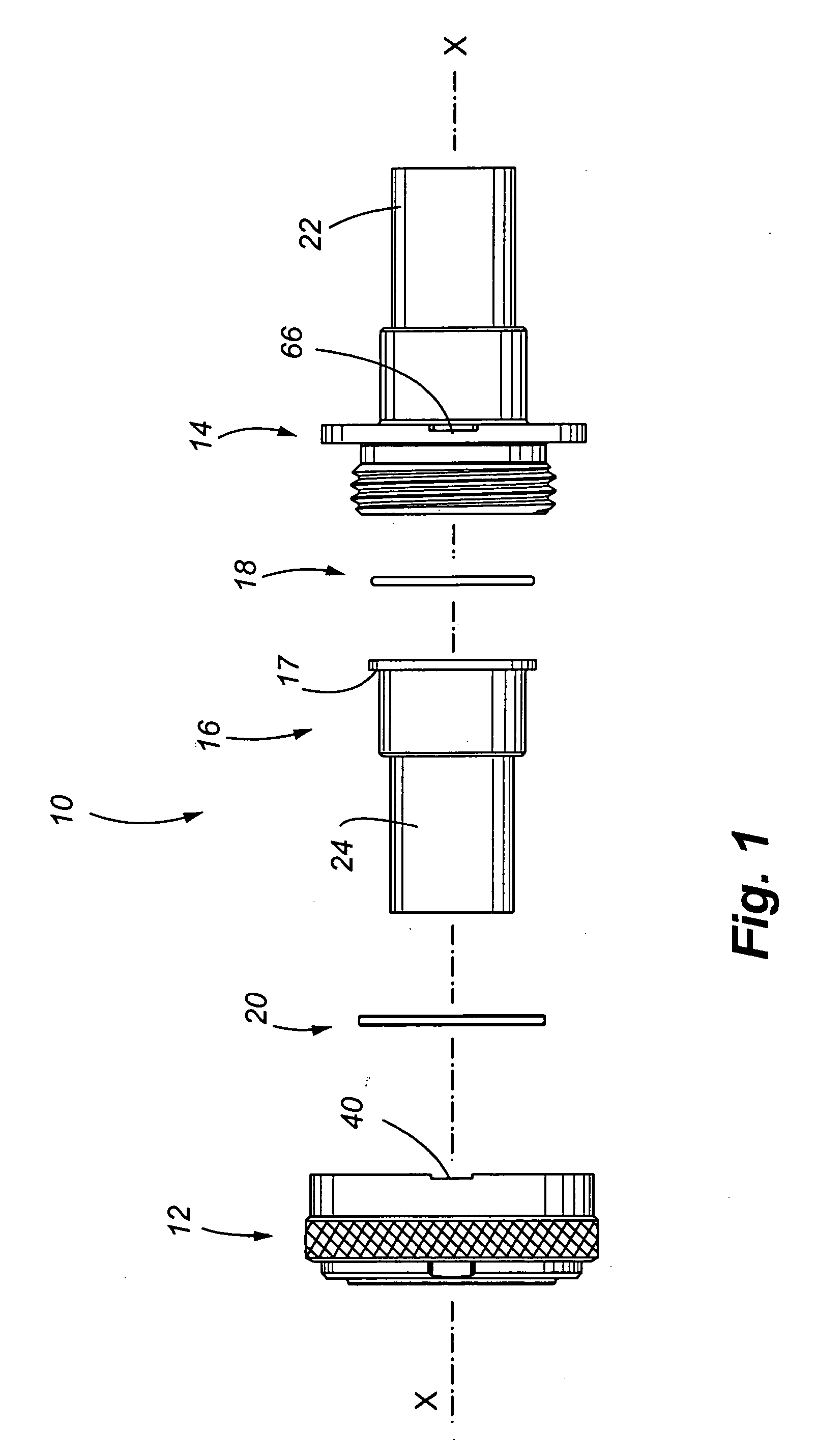
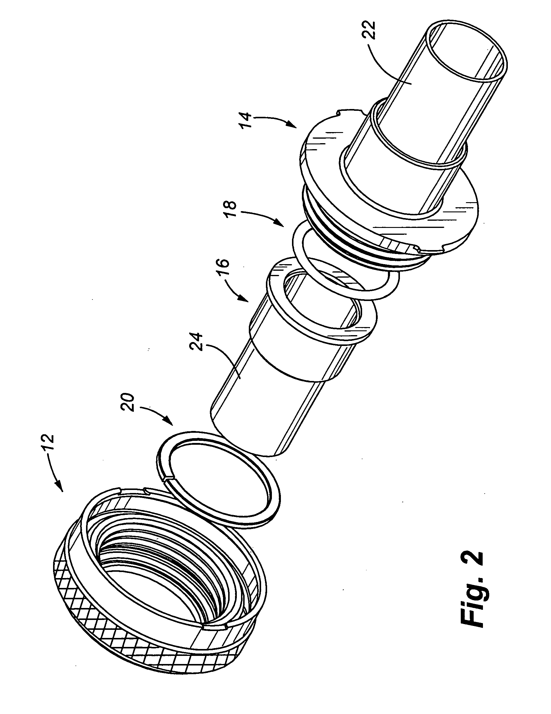
[0035]FIGS. 1 and 2 illustrate the coupling assembly 10 of the present invention for rigidly connecting confronting ends of two conduit members.

[0036] Basic or primary components of the coupling assembly include a threaded flange or first coupling member 14, a lock nut group or second coupling member 12, a standard flange 16, an o-ring 18 positioned between a facing surface of the standard flange and a facing surface of the threaded flange, and a rigid connecting means or flat washer 20 that is positioned at the interface between the lock nut group and the standard flange.

[0037] Assembly of the coupling assembly includes placement of the flat washer 20 within the lock nut group and alignment with the opening of the lock nut group, and positioning the lock nut group over the standard flange so that when assembled, the flat washer 20 is trapped between an exterior shoulder 17 of the standard flange and an interior shoulder 45 of the nut body 44, as further discussed below.

[0038] Th...


PUM


Abstract

A coupling assembly is provided for releasably interconnecting confronting ends of conduit members. The coupling assembly creates a self-locking, and self-bonding connection wherein locking and unlocking is achieved by a predetermined amount of rotation of a lock nut group with respect to a stationary threaded flange. The overall construction of the coupling assembly creates the rigid connection between the conduit members, yet adequate sealing between the conduit members is provided by a single sealing member.

Description

FIELD OF THE INVENTION [0001] This invention relates to a coupling assembly for interconnecting two members, and more particularly, to a self-locking, self-bonding, rigid coupling assembly for interconnecting a pair of tubular conduit members wherein the coupling assembly has a releasable locking feature for connection and disconnection. BACKGROUND OF THE INVENTION [0002] The owner of the current invention is also the owner of a number of previous patents for couplings used to interconnect confronting ends of fluid carrying conduits in an aircraft. These patents include the U.S. Pat. Nos. 5,871,239; 6,050,609; and 6,073,973. Characteristics common to each of the inventions disclosed in these patents are coupling devices that include a plurality of threaded members which are rotatable in a locking direction, and rotatable in an opposite unlocking direction. Locking of the couplings is achieved by locking tabs that are received in corresponding notches / reliefs. A resilient member is p...

Claims


Application Information

Patent Timeline
Patent Type & Authority Applications(United States)
IPC IPC(8): F16L19/00
CPCF16L19/005F16L25/01
Inventor BREAY, CLIFTON P.
Owner EATON INTELLIGENT POWER LTD
Why Eureka
Try Eureka