
Fuse resistance read-out circuit

Active Publication Date: 2007-03-08
CHANGXIN MEMORY TECH INC
View PDF4 Cites 11 Cited by
  • Summary
  • Abstract
  • Description
  • Claims
  • Application Information

AI Technical Summary

Benefits of technology

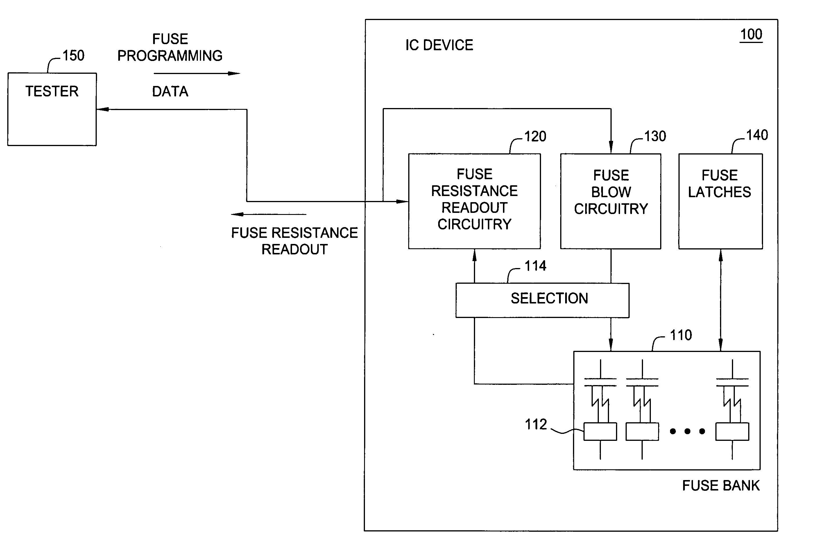
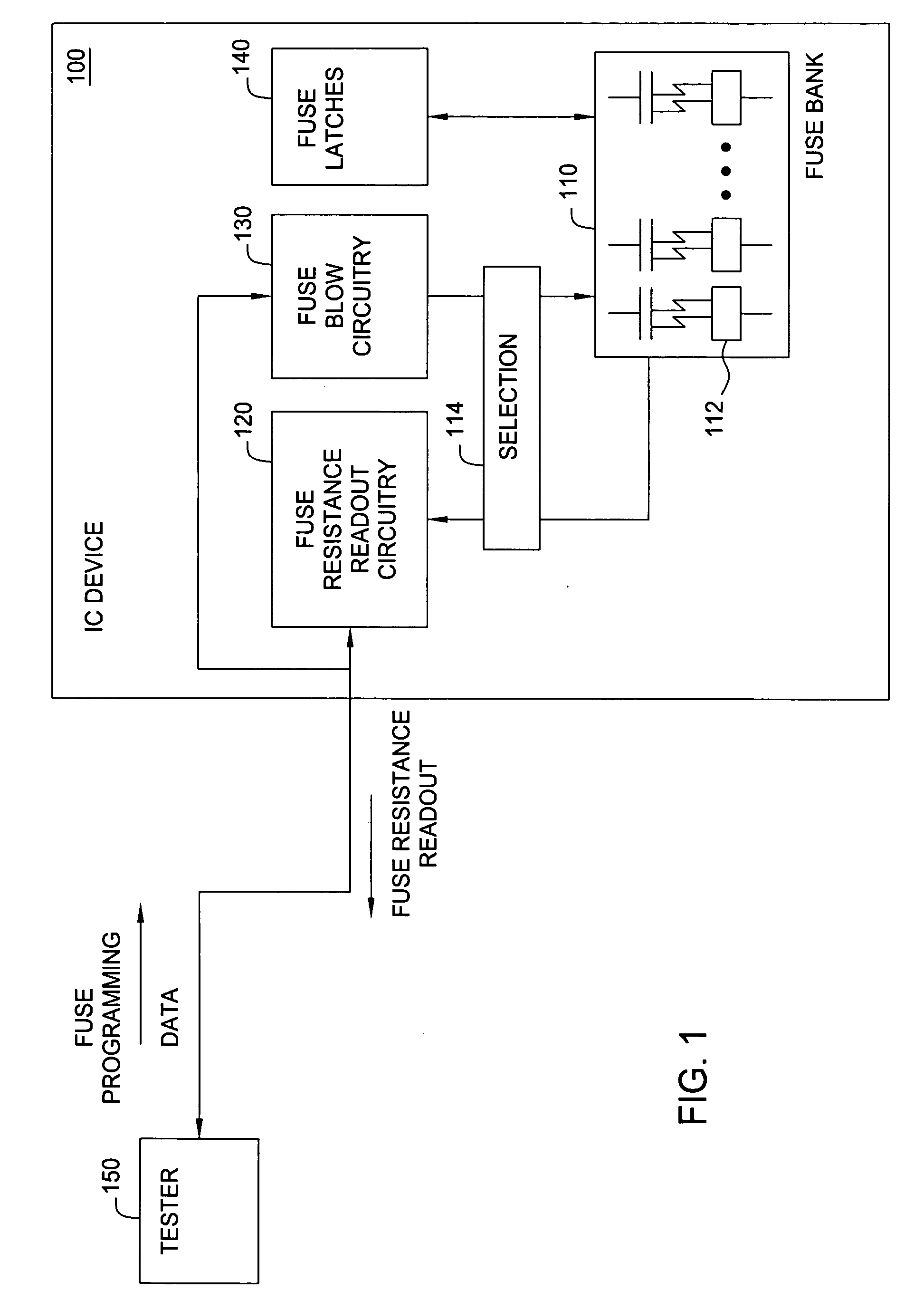
[0009] Embodiments of the invention generally provide methods and apparatus for reading out fuse resistance.
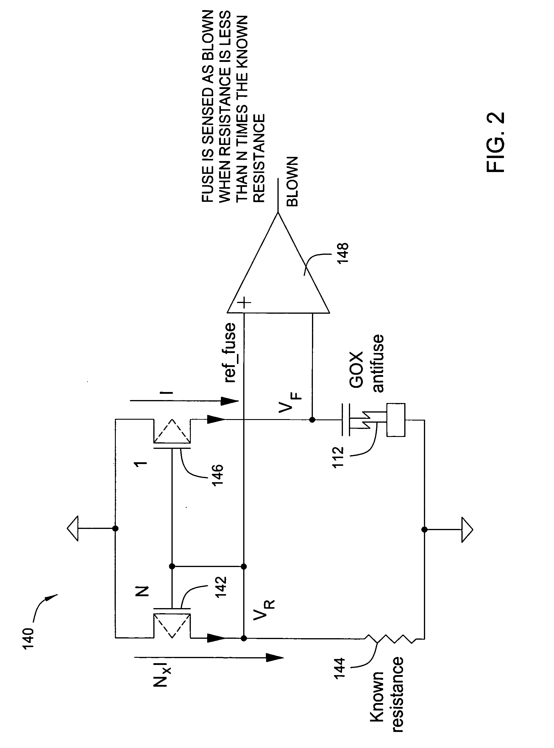
[0010] One embodiment provides a method for providing an indication of a resistance of a programmable fuse element within an integrated circuit device. The method generally includes (a) adjusting an effective reference resistance, (b) comparing the resistance across the fuse to the effective reference resistance, (c) if an outcome of the comparison is a first result, repeating steps (a) and (b), and (d) if the outcome of the comparison is a second result, providing an indication of the effective reference resistance.
[0011] Another embodiment provides a method for obtaining a digital readout of a resistance of a programmable fuse element within an integrated circuit device. The method generally includes (a) adjusting a number of transistors connected in parallel to control a current flow through a resistor having a known resistance, (b) monitoring an output of a comparator circuit that compares a voltage across the fuse element to a voltage across the resistor, (c) if the output of the comparator circuit is in a first state, repeating steps (a) and (b), and (d) if the output of the comparator circuit is in a second state, providing the number of transistors connec

Problems solved by technology

In certain circumstances, possibly caused by changes in the element structure or programming voltage due to manufacturing process variations, the decrease in resistance of an antifuse may not be sufficient for this sensing circuitry to determine the antifuse has been blown.
Unfortunately, a detailed characterization of the fuse resistances is not possible from this binary indication.
However, in the field, changes in operating conditions may cause these fuses to be detected as not blown by the fuse latch circuits, which may cause erroneous device operation and possibly catastrophic failure.

Method used


Image

  • Fuse resistance read-out circuit
  • Fuse resistance read-out circuit
  • Fuse resistance read-out circuit

Examples


Embodiment Construction

[0022] Embodiments of the invention generally provide methods and apparatus a more precise readout of fuse resistance than that provided by a conventional binary (blown / not-blown) readout. For some embodiments, a “stepped” digital readout of fuse resistance may be obtained by selectively altering an effective reference resistance to which the fuse resistance is compared. For some embodiments, a direct analog readout may be obtained in addition, or instead of, a digital resistance readout.

[0023] To facilitate understanding, embodiments may be described below with reference to memory devices, such as DRAM devices, as a specific, but not limiting example of an application in which the techniques of reading out fuse resistance described herein may be used to advantage. However, those skilled in the art will recognize these techniques may be applied in a wide variety of devices that utilize fuses for various reasons. Further, while embodiments may be described with reference to anti-fus...


PUM


Abstract

Methods and apparatus for a more precise readout of fuse resistance than a conventional binary readout are provided. For some embodiments, a digital readout of fuse resistance may be obtained by selectively altering an effective reference resistance to which the fuse resistance is compared. For some embodiments, a direct analog readout may be obtained in addition, or instead of, a digital resistance readout

Description

BACKGROUND OF THE INVENTION [0001] 1. Field of the Invention [0002] The invention generally relates to integrated circuit devices utilizing fuse elements and, more particularly, to techniques for reading out the resistance of such fuse elements after a blow process. [0003] 2. Description of the Related Art [0004] Fuses are used in integrated circuit (IC) devices for a variety of reasons. As an example, in dynamic random access memory (DRAM) devices, fuses are often used to select redundant circuits to replace failing memory elements, as well as trim various timing and voltage generations circuits. As used herein, the term fuse generally refers to an element whose associated resistance is changed significantly after the element is physically altered (hereinafter “blown”), for example by “cutting” the element with a laser or applying a predetermined programming or “blow” voltage across the element. [0005] Fuses whose resistance is decreased after being blown are generally referred to ...

Claims


Application Information

Patent Timeline
IPC IPC(8): G11C17/18
CPCG11C17/18G11C29/50008G11C29/027G11C29/02
Inventor VOGELSANG, THOMAS
Owner CHANGXIN MEMORY TECH INC
Learn More