
Multi-service communication system

Inactive Publication Date: 2007-03-08
ETHERNITY NETWORKS
View PDF7 Cites 17 Cited by
  • Summary
  • Abstract
  • Description
  • Claims
  • Application Information

AI Technical Summary

Benefits of technology

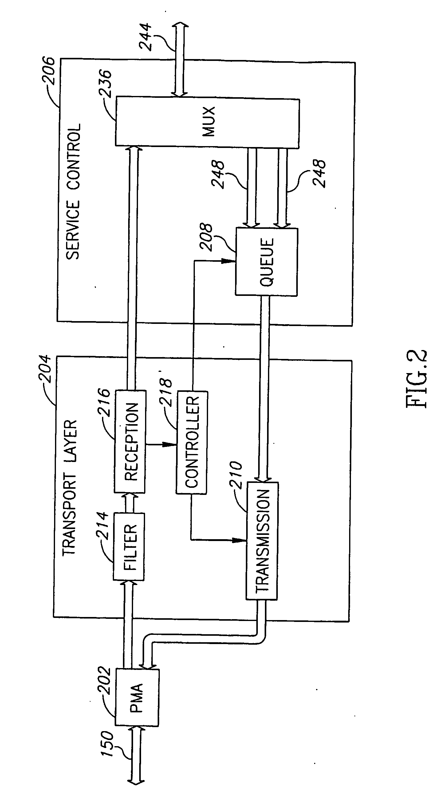
[0009] An aspect of some embodiments of the invention relates to dynamic allocation of bandwidth of a backplane bus in a rack system, using in-band instructions. A master unit optionally collects information on the bandwidth needs of line cards in the system and synchronously allocates time slots according to the needs. Optionally, the allocation is performed by in-band transmission on the bus lines used for data transmission. The in-band transmission of the instructions achieves a better utilization rate of the bus. In addition, in band transmission allows simpler use of standard buses planned for static bandwidth allocation. It is noted that the term bandwidth refers herein, as customary in the art, to the capacity of the bus, such that the bandwidth allocation referred to herein may include time division, frequency division, code division and / or any other division of the bus capacity (e.g., a combination of time and frequency).
[0010] In some embodiments of the invention, the master periodically transmits an allocation for a plurality of slots on the bus, in a broadcast message. Transmission of the allocation for a plurality of slots together, reduces the bandwidth wasted on allocation messages. A single allocation message is used to instruct a plurality of different cards, on the bandwidth they are to use. In some embodiments of the invention, each allocation message relates to bandwidth of more than 100 μseq, optionally 125 μsec, 256 μsec or 1000 μsec. Optionally, the amount of the bandwidth to which each allocation message relates is configurable. Alternatively or additionally, the amount of the bandwidth to which each allocation message relates is dynamically adjusted by the master for example according to the type of traffic passing on the bus.
[0020] An aspect of some embodiments of the invention relates to transmitting signals of a plurality of different formats on a backplane bus or star of a rack system, encapsulated in a format using large packets, i.e., above 500 bytes, for example the Ethernet format. When the signals reach their destination in one of the cards at the other end of the backplane bus, the encapsulation is removed. Using the Ethernet encapsulation simplifies the encapsulation as there is no need for packet fragmentation. In addition, the use of Ethernet encapsulation allows operation on legacy Ethernet rack systems.
[0027] There is further provided in accordance with an exemplary embodiment of the invention, a network card of a rack system, comprising a link interface adapted to connect to a backplane link of the rack system, a data interface adapted to receive data signals through the link interface from the backplane link, a network bus interface for transmitting data signals received by the data interface onto a network bus and a controller adapted to generate control signals regulating the use of the backplane link, for transmission to other cards connected to the backplane link, the control signals being timed responsive to the bandwidth of the network bus, such that the signals received by the data interface can be forwarded onto the network immediately upon receipt without queuing.

Problems solved by technology

The bus is pre-allocated between the various types of traffic and does not accommodate to changing needs of the different formats.
Some of these systems, although including different service types in a single box, require separate development of the plurality of different system types, so that the development costs remain relatively high.

Method used


Image

  • Multi-service communication system
  • Multi-service communication system
  • Multi-service communication system

Examples


Embodiment Construction

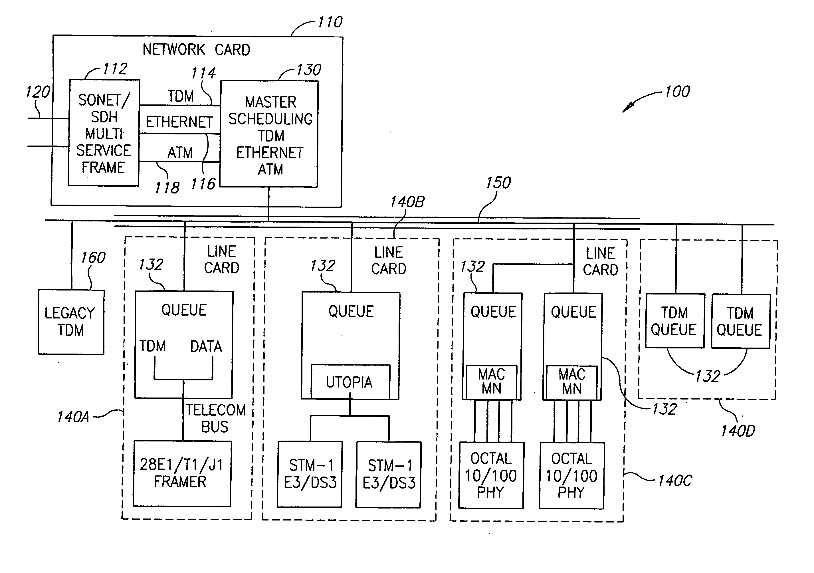
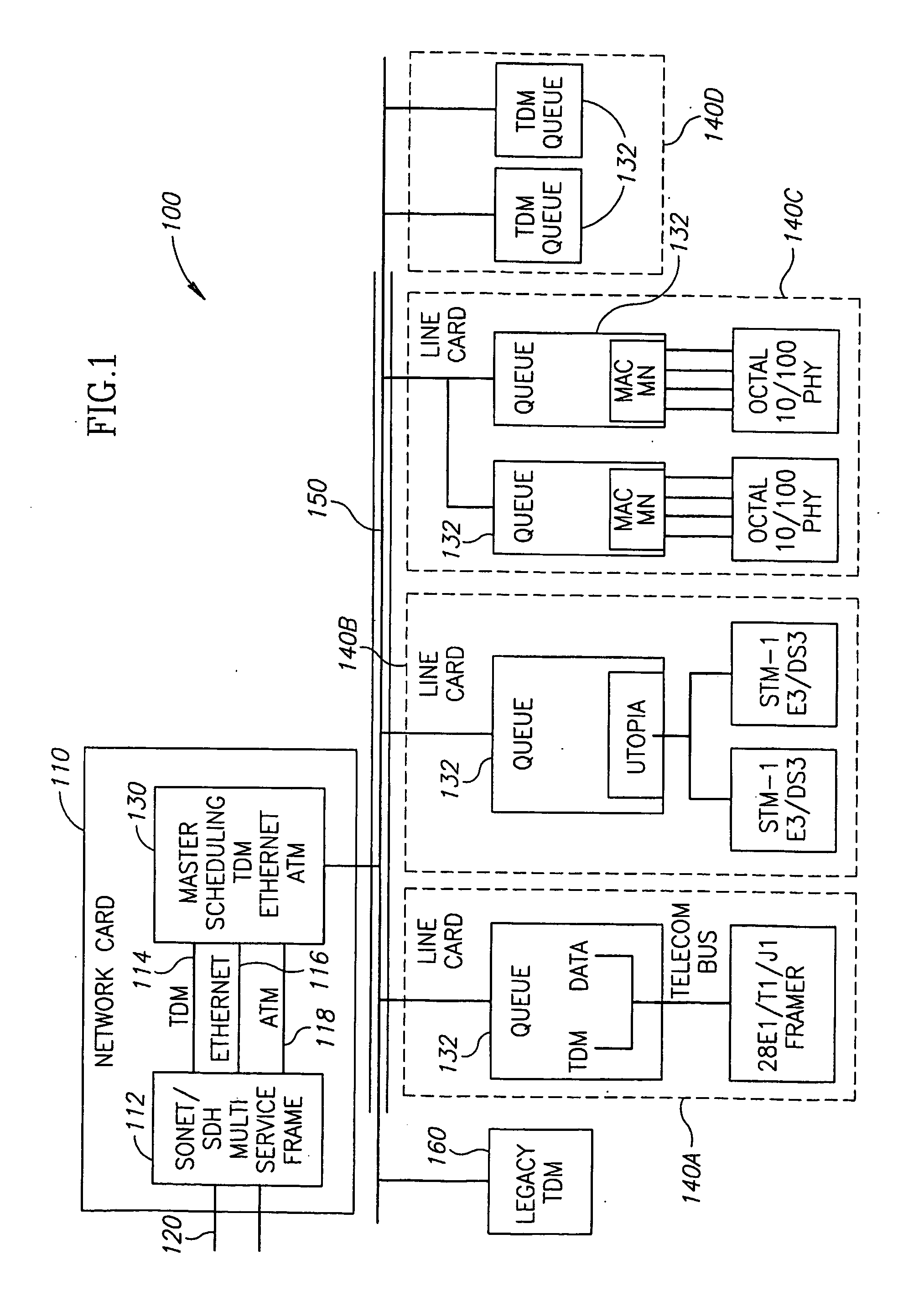
[0049]FIG. 1 is a schematic diagram of a rack system 100, in accordance with an exemplary embodiment of the invention. A network card 110 includes a multi service framer 112, for example a SONET or an SDH framer, which transfers signals in various formats onto a network bus 120, as is known in the art. In the example of FIG. 1, framer 112 includes a TDM interface 114, an Ethernet interface 116 and an ATM interface 118. It will be understood that other signal framings may be used, including the token ring format. Network card 110 receives the signals of different formats, over a rack bus 150, from line cards 140 (marked 140A, 140B, etc.) which in turn collect the signals from clients. In addition, signals are passed in the other direction, from network bus 120 to line cards 140. Optionally, each line card 140 handles signals of a single format. Alternatively, one or more line cards 140 handle signals of a plurality of formats, as discussed below with reference to FIG. 2. In FIG. 1, l...


PUM


Abstract

A network card of a rack system. The card includes a bus interface adapted to connect to a backplane bus of the rack system, a data interface adapted to transmit data signals through the bus interface onto the backplane bus and a controller adapted to periodically generate bandwidth allocation signals indicating allocation of time slots of the backplane bus, and transmitting the allocation signals through the bus interface on the backplane bus, on same bus lines used by the data interface.

Description

FIELD OF THE INVENTION [0001] The present invention relates to the field of communications and particularly to multi-service communication systems. BACKGROUND OF THE INVENTION [0002] Communications are used for many different tasks, including telephone conversations, transmission of video signals, fax documents and Internet web pages. Several different types of networks are used for communications. Synchronous time domain multiplexed (TDM) links carry signals synchronously and are traditionally used for telephone services. Ethernet links carry asynchronous, relatively long, packets. Traditionally, Ethernet links are used in connecting computers to each other. Asynchronous transfer mode (ATM) links carry short cells, which can carry different types of transmissions. Different networks developed in order to provide users with the different services. In recent years, however, many communication service providers want or need to provide all three of these types of services. [0003] Commu...

Claims


Application Information

Patent Timeline
IPC IPC(8): H04L12/28H04L12/64
CPCH04L12/6402H04L49/40H04L49/606H04L49/604H04L49/602
Inventor LEVI, DAVID
Owner ETHERNITY NETWORKS
Learn More