Composite materials including nickel-based matrix materials and hard particles, tools including such materials, and methods of using such materials

a nickel-based matrix material and composite material technology, applied in the field of composite materials including nickel-based matrix materials and hard particles, tools including such materials, and methods of using such materials, can solve the problems of small vugs, voids and other defects in the exposed surface of the bonding material, solids-laden drilling fluid, and further erode, abrade and enlarge the small vugs and voids in the bonding material

Active Publication Date: 2007-03-15
BAKER HUGHES INC
View PDF99 Cites 71 Cited by
  • Summary
  • Abstract
  • Description
  • Claims
  • Application Information

AI Technical Summary

Problems solved by technology

During use, small vugs, voids and other defects may be formed in exposed surfaces of the bonding material 24 due to wear.
Solids-laden drilling fluids and formation debris generated during the drilling process may further erode, abrade and enlarge the small vugs and voids in the bonding material 24.
Loss of a cutting element 22 during a drilling operation can lead to rapid wear of other cutting elements and catastrophic failure of the entire drill bit 10.
The materials of an ideal drill bit must be extremely hard to efficiently shear away the underlying earth formations without excessive wear.
In practicality, however, materials that exhibit extremely high hardness tend to be relatively brittle and do not exhibit high fracture toughness, while materials exhibiting high fracture toughness tend to be relatively soft and do not exhibit high hardness.

Method used


Image

  • Composite materials including nickel-based matrix materials and hard particles, tools including such materials, and methods of using such materials
  • Composite materials including nickel-based matrix materials and hard particles, tools including such materials, and methods of using such materials
  • Composite materials including nickel-based matrix materials and hard particles, tools including such materials, and methods of using such materials

Examples


Embodiment Construction

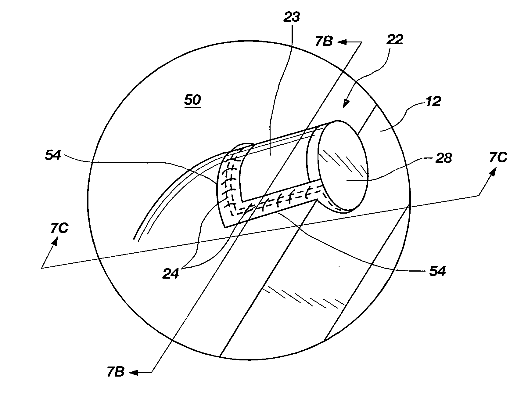
[0037] The illustrations presented herein, with the exception of FIG. 9, are not meant to be actual views of any particular material, apparatus, system, or method, but are merely idealized representations which are employed to describe the present invention. Additionally, elements common between figures may retain the same numerical designation.

[0038]FIG. 5 represents a polished and etched surface of an abrasive wear-resistant material 54 that embodies teachings of the present invention. FIG. 9 is an actual photomicrograph of a polished and etched surface of an abrasive wear-resistant material that embodies teachings of the present invention. Referring to FIG. 5, the abrasive wear-resistant material 54 includes a plurality of sintered tungsten carbide pellets 56 and a plurality of cast tungsten carbide granules 58 substantially randomly dispersed throughout a matrix material 60. Each sintered tungsten carbide pellet 56 may have a generally spherical pellet configuration. The term “...


PUM

PropertyMeasurementUnit
melting pointaaaaaaaaaa
melting temperatureaaaaaaaaaa

Abstract

An abrasive wear-resistant material includes a matrix and sintered and cast tungsten carbide granules. A device for use in drilling subterranean formations includes a first structure secured to a second structure with a bonding material. An abrasive wear-resistant material covers the bonding material. The first structure may include a drill bit body and the second structure may include a cutting element. A method for applying an abrasive wear-resistant material to a drill bit includes providing a bit, mixing sintered and cast tungsten carbide granules in a matrix material to provide a pre-application material, heating the pre-application material to melt the matrix material, applying the pre-application material to the bit, and solidifying the material. A method for securing a cutting element to a bit body includes providing an abrasive wear-resistant material to a surface of a drill bit that covers a brazing alloy disposed between the cutting element and the bit body.

Description

PRIORITY CLAIM [0001] This application is a continuation-in-part of application Ser. No. 11 / 223,215, which was filed Sep. 9, 2005, and is currently pending, the contents of which are incorporated herein in their entirety by this reference.TECHNICAL FIELD [0002] The present invention generally relates to earth-boring drill bits and other tools that may be used to drill subterranean formations, and to abrasive, wear-resistant hardfacing materials that may be used on surfaces of such earth-boring drill bits. The present invention also relates to methods for applying abrasive wear-resistant hardfacing materials to surfaces of earth-boring drill bits, and to methods for securing cutting elements to an earth-boring drill bit. BACKGROUND [0003] A typical fixed-cutter, or “drag,” rotary drill bit for drilling subterranean formations includes a bit body having a face region thereon carrying cutting elements for cutting into an earth formation. The bit body may be secured to a hardened steel ...

Claims


Application Information

Patent Timeline
Patent Type & Authority Applications(United States)
IPC IPC(8): E21B10/36
CPCB22F7/062B22F2005/001E21B10/573E21B10/46C22C29/08
Inventor OVERSTREET, JAMES L.
Owner BAKER HUGHES INC
Why Eureka
Try Eureka