Lens-attached ligh-emitting element and method for manufacturing the same

a technology of ligh-emitting elements and lenses, which is applied in the field of lenses-attached light-emitting elements, can solve the problems of low optical availability efficiency, the above-described problem is applied, and the optical availability efficiency of the array of light-emitting elements cannot be fully increased, so as to achieve the effect of improving the optical availability efficiency of the array of light-emitting elements

Inactive Publication Date: 2007-03-15
FUJIFILM BUSINESS INNOVATION CORP
View PDF10 Cites 21 Cited by
  • Summary
  • Abstract
  • Description
  • Claims
  • Application Information

AI Technical Summary

Benefits of technology

[0008] An object of the present invention is to improve the optical availability efficiency of a light-emitting element array used for an optical printer in which the light-emitting area of the light-emitting element array is imaged on a photosensitive drum through a lens array.

Problems solved by technology

This means that only the 95-97% of the light emitted by the LED is not utilized, resulting in a problem of a low optical availability efficiency.
However, the area neighbored to the optical axis corresponds to the position of the electrode 20, resulting in the problem such that the optical availability efficiency may not be fully increased.
However, these publications have not discussed such a problem and the shape of a micro lens.
It is noted that the above-described problem is applied not only to an LED but also another light-emitting element.

Method used


Image

  • Lens-attached ligh-emitting element and method for manufacturing the same
  • Lens-attached ligh-emitting element and method for manufacturing the same
  • Lens-attached ligh-emitting element and method for manufacturing the same

Examples


embodiment 1

[0068] EMBODIMENT 1

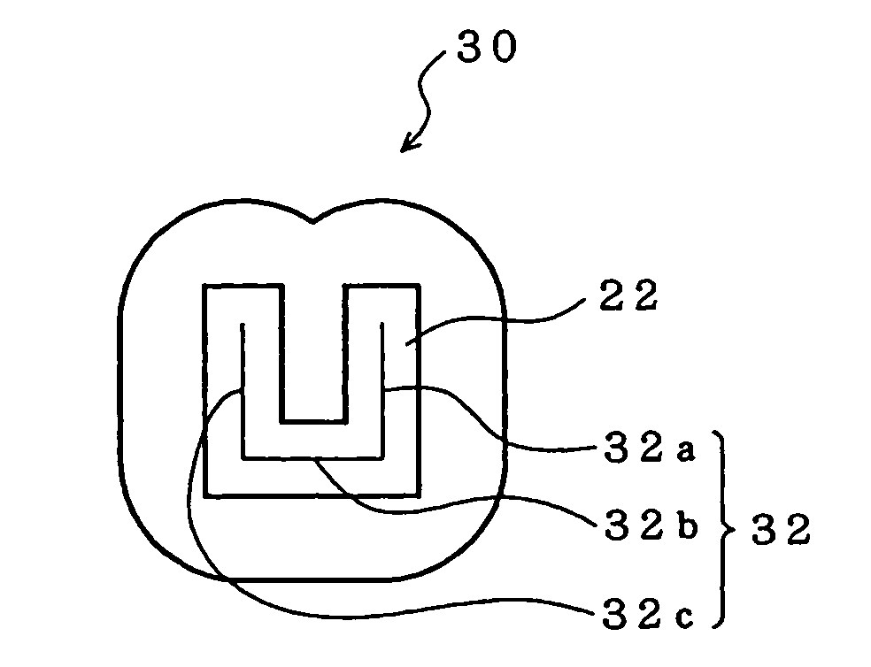
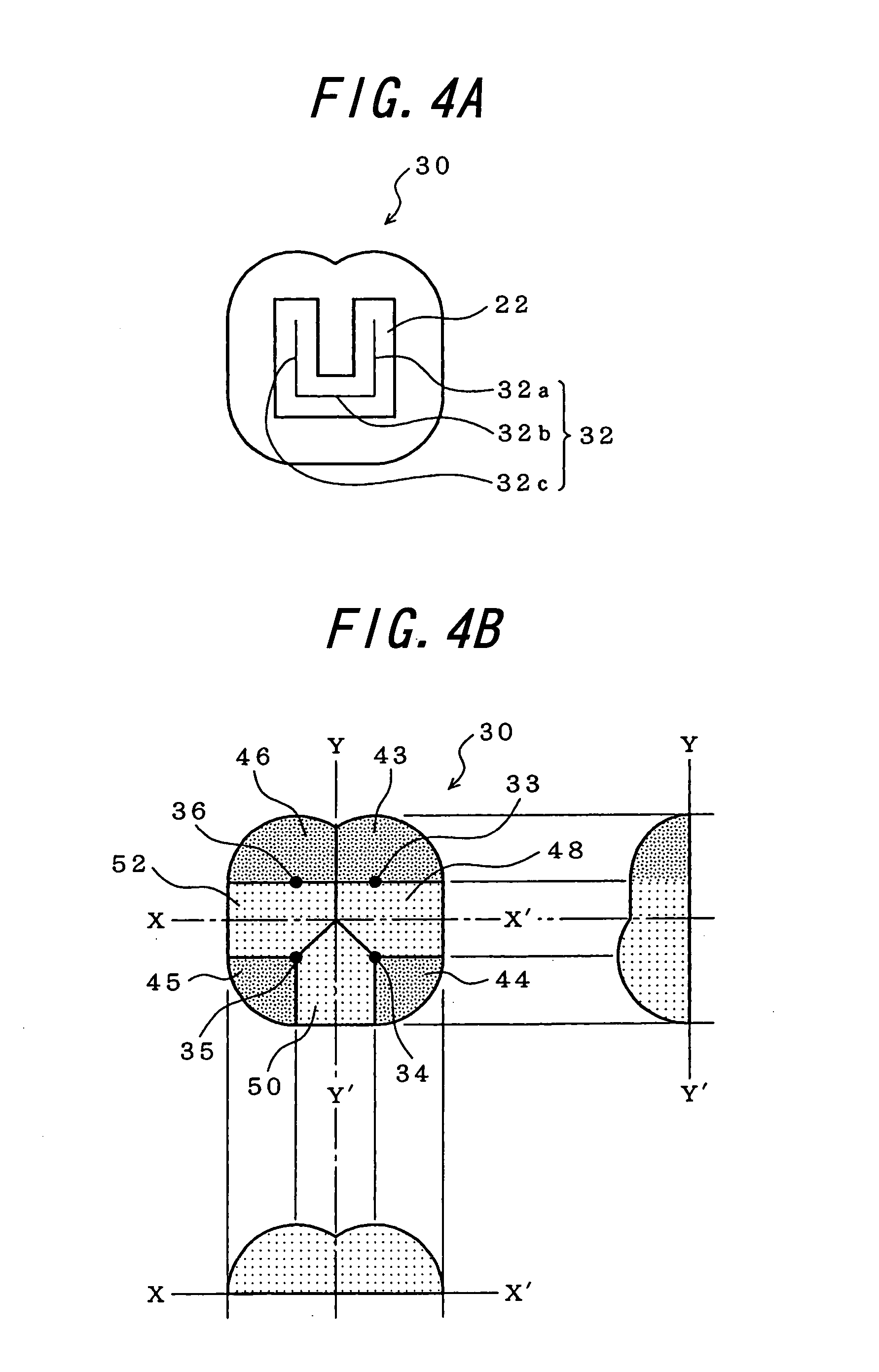
[0069] In a lens-attached light-emitting element in accordance with the present invention, a composite lens 30 is provided on an approximately U-shaped light-emitting area 22 of an LED as shown in FIG. 4A.

[0070] If the positions where light intensity is maximum in the approximately U-shaped light-emitting area 22 are fastened, then a U-shaped polygonal line 32 consisting of three segments is imagined. Four parts of spherical lens are arranged in such a manner that each center thereof is at the both ends or the neighborhood of the both ends of respective three segments of the polygonal line 32, and three parts of cylindrical lens are arranged between two parts of spherical lens, respectively, each cylindrical lens having an axis parallel with said each segment. These four parts of spherical lens and three partial cylindrical lens are neighbored together to constitute the composite lens 30.

[0071] As the material for the composite lens, an epoxy resin or acrylic re...

embodiment 2

[0086] EMBODIMENT 2

[0087] In the embodiment 1, the case that a light-emitting element array is an LED array has been described.

[0088] In the present embodiment, “a self-scanning light-emitting element array” is used as a light-emitting element array. The improvement of an optical availability efficiency was appreciated as in the embodiment 1.

[0089] The self-scanning light-emitting element array is configured such that a self-scanning function of light-emitting elements is implemented by utilizing a light-emitting thyristor of pnpn structure as a component of the light-emitting element array. Such self-scanning light-emitting element array has been disclosed in Japanese Patent Publication Nos. 1-238962, 2-14584, 2-92650, and 2-92651. Japanese Patent Publication No. 2-263668 has disclosed a self-scanning light-emitting element array having such a structure that a shift part including a transfer element array and a light-emitting part including a light-emitting element array are sepa...


PUM


Abstract

A lens-attached light-emitting element having an improved optical availability efficiency includes a composite lens provided on an approximately U-shaped light-emitting area of the light emitting element array. Four spherical lenses are arranged in such a manner that each is centered in the neighborhood the an end of a respective one of three segments of a U-shaped polygonal line corresponding to positions where light emitted by the U-shaped light-emitting area is a maximum Three cylindrical lens are arranged between two of the spherical lens, respectively, each cylindrical lens having an axis parallel with each segment. These four spherical lenses and three cylindrical lenses together constitute the composite lens. The light-emitting element further comprises an antireflection film covering the light-emitting area, and the composite lens is formed on the surface of the antireflection film.

Description

TECHNICAL FIELD [0001] The present invention relates to a lens-attached light-emitting element, particularly to a lens-attached light-emitting element having an improved optical availability efficiency and a method for manufacturing the lens-attached light-emitting element. BACKGROUND ART [0002] An optical system of a writing head in an optical printer is usually designed so that an image of light spot of respective LEDs, (Light-Emitting Diode) constructing an LED array is focused on a photosensitive drum through a lens array. As a lens array, a distributed index rod lens array is often used. [0003] A typical construction of an LED array, a distributed index rod lens array, and a photosensitive drum used in a conventional optical printer is shown in FIG. 1. In the figure, the LED is designated by reference numeral 10, the rod lens array by reference numeral 12, and the photosensitive drum by reference numeral 14. [0004] An effective aperture angle θ of the lens array 12 is in the ra...

Claims


Application Information

Patent Timeline
Patent Type & Authority Applications(United States)
IPC IPC(8): H01L33/00B41J2/45H01L27/15
CPCH01L27/153B41J2/451
Inventor HAMANAKA, KENJIROHASHIMOTO, TAKAHIRONAGATA, HIDESHIOHNO, SEJIMURAGUCHI, ISAOKOMABA, NOBUYUKI
Owner FUJIFILM BUSINESS INNOVATION CORP
Why Eureka
Try Eureka