
External conductive heat dissipating device for microcomputers

a heat dissipating device and microcomputer technology, applied in the direction of electrical apparatus casings/cabinets/drawers, cooling/ventilation/heating modifications, instruments, etc., can solve the problems that the heat dissipation of the cpu and related chips cannot be achieved by the traditional heat sink that comes with a fan, and the relatively tall structure no longer meets the requirements of the heat dissipation device for the microcomputer system, so as to reduce the siz

Inactive Publication Date: 2007-03-15
KING YOUNG TECH
View PDF9 Cites 37 Cited by
  • Summary
  • Abstract
  • Description
  • Claims
  • Application Information

AI Technical Summary

Benefits of technology

[0005] Therefore, it is a primary objective of the present invention to overcome the shortcomings of the prior art by providing an external conductive heat dissipating device for microcomputers, and more particularly to a heat dissipating device that uses the application environment of the heat dissipating board and a special heat dissipating structure to quickly dissipate the heat from the heat dissipating chassis to the outside, so as to achieve the effects of meeting the requirements of the applications of the microcomputer system, reducing the size of the microcomputers, shortening the thermal conduction distance, and improving the heat dissipating performance.

Problems solved by technology

The heat dissipation of the CPU and related chips cannot be achieved by the traditional heat dissipating device for desktop computers.
In other words, the prior art heat sink that comes with a fan and a relatively tall structure no longer meets the requirements of the heat dissipating device for microcomputer systems.

Method used


Image

  • External conductive heat dissipating device for microcomputers
  • External conductive heat dissipating device for microcomputers
  • External conductive heat dissipating device for microcomputers

Examples


Embodiment Construction

[0010] To make it easier for our examiner to understand the objective of the invention, its structure, innovative features, and performance, we use a preferred embodiment together with the attached drawings for the detailed description of the invention.

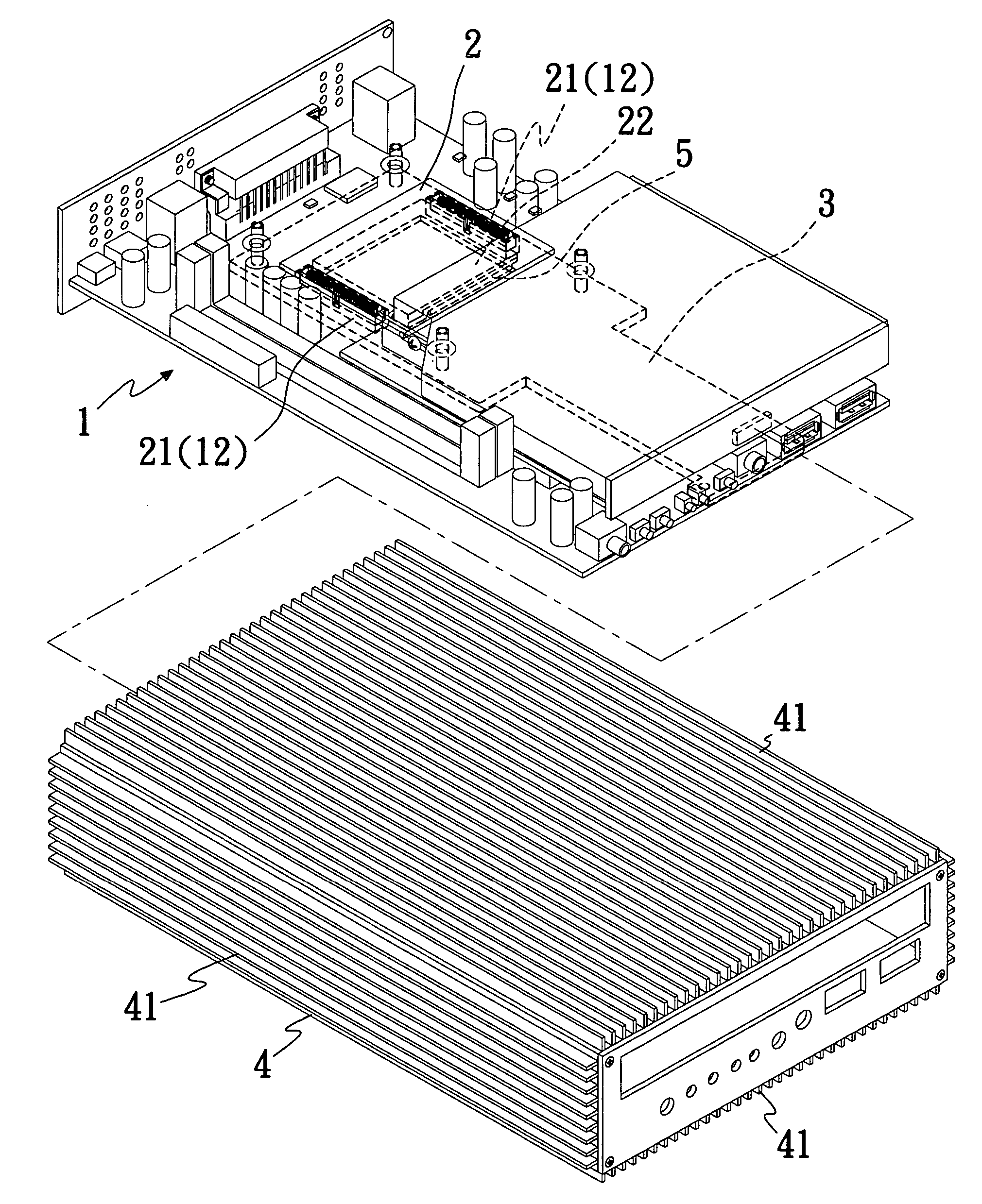
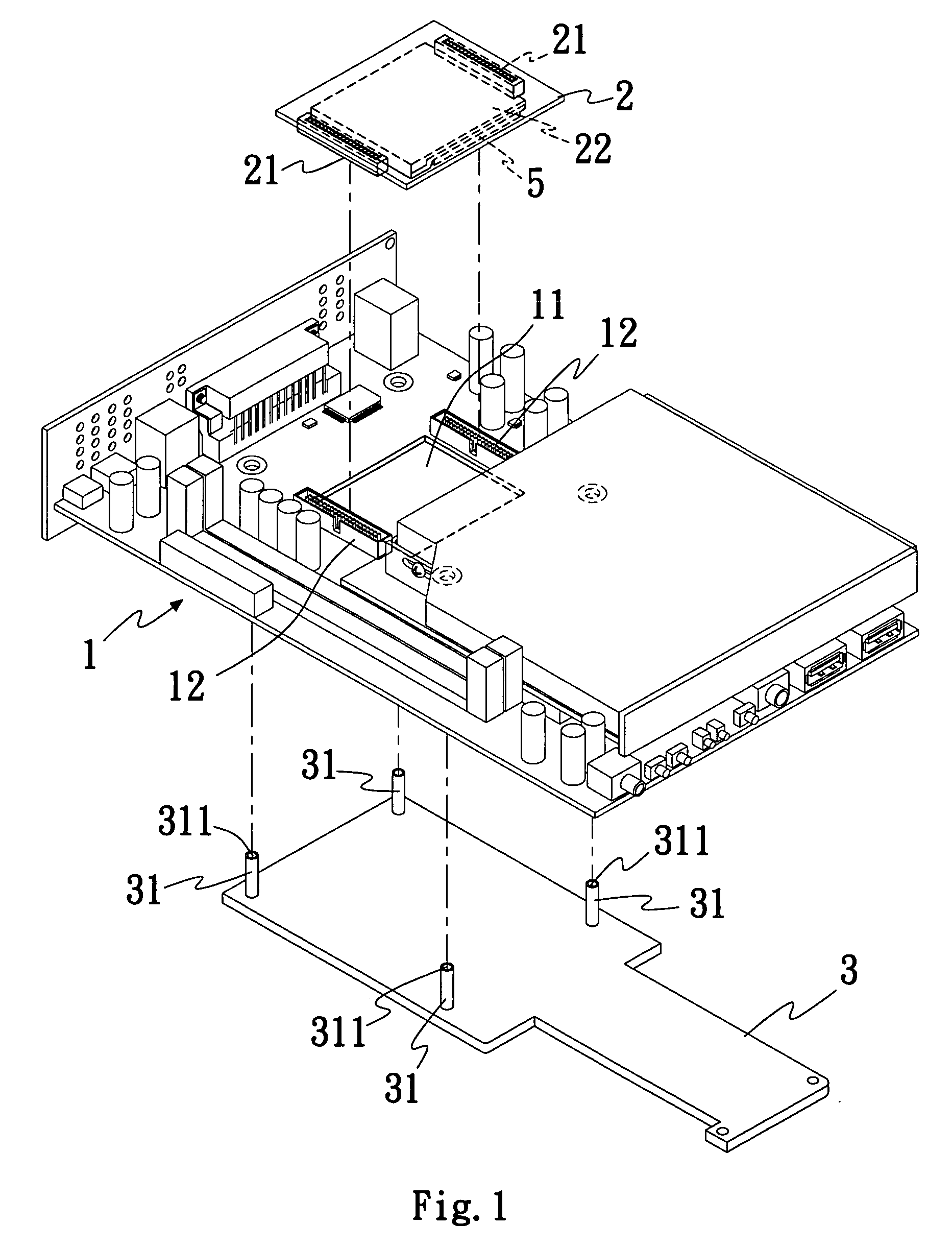
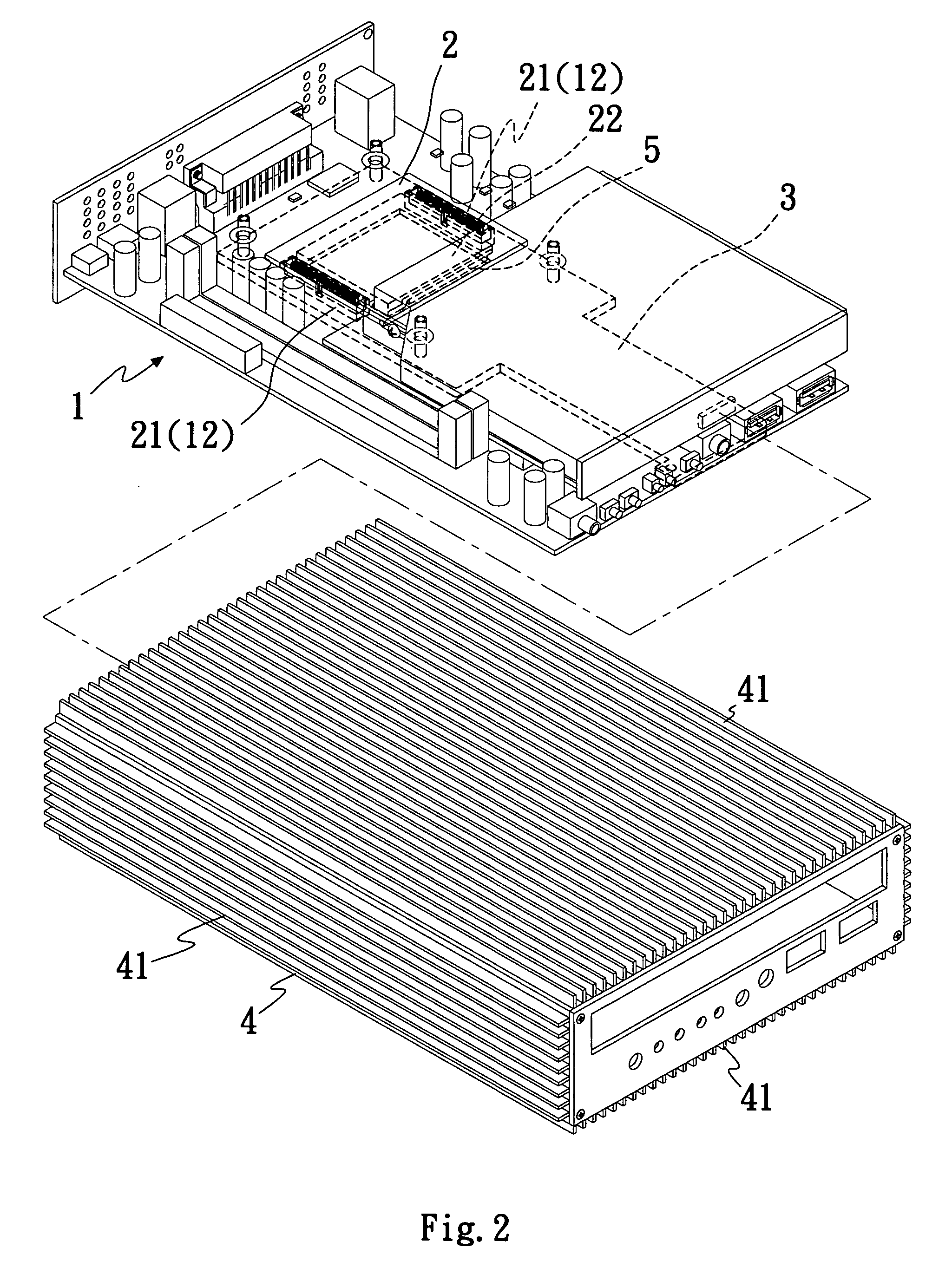
[0011] An external conductive heat dissipating device for microcomputers of the present invention as shown in the figures comprises a motherboard 1, an adapter board 2, a heat dissipating board 3, and a heat dissipating chassis 4 of a microcomputer.

[0012] Referring to FIG. 1, a motherboard 1 is a circuit board of a special specification for microcomputers, and the motherboard 1 includes various chips (such as a display chip, an audio chip, and a network chip), various interface slots, ports, and other necessary electronic components installed at the front side of the motherboard 1, and the motherboard 1 is provided for installing a central processing unit (CPU). These components are prior art components and thus will not be describe...


PUM


Abstract

A conductive heat dissipating device for microcomputers includes a motherboard having an opening and a first electric connector installed adjacent to the front side of the opening, an adapter board having a second electric connector connected to the first electric connector on the front side of the opening, a processor soldered at the back of the adapter board or a third electric connector for inserting a processor, such that the processor is placed upside down into the opening, and a heat dissipating board connected to the back of the motherboard and in contact with the surface of the processor, and the heat dissipating board is in contact with a special heat dissipating structure in a chassis to define an external conductive heat dissipating device capable of dissipating the heat to the outside, reducing the size of the microcomputer, shortening the distance of thermal conduction, and improving the heat dissipation.

Description

FIELD OF THE INVENTION [0001] The present invention relates to an external conductive heat dissipating device for microcomputers, and more particularly to a conductive heat dissipating device capable of conducting the heat produced by a processor or other chips of a microcomputer to a chassis of the microcomputer. BACKGROUND OF THE INVENTION [0002] As the computer technology advances, particularly the nano technology and chip precision packaging technology are well developed, a single chip usually comes with powerful computation and storage functions, and the single chip becomes very compact, so that a motherboard can install many onboard application specific integrated circuits. Besides simplifying the complicated structure or process of installing display cards, sound cards, network cards, and other special function cards onto a motherboard of a desktop computer, the onboard design also can reduce the size and specification of the motherboard and give a compact and multifunctional...

Claims


Application Information

Patent Timeline
IPC IPC(8): H05K7/20G06F1/20
CPCG06F1/20H05K7/20509H05K7/20409
Inventor CHENG, WAN CHEN
Owner KING YOUNG TECH
Features
  • Generate Ideas
  • Intellectual Property
  • Life Sciences
  • Materials
  • Tech Scout
  • Unparalleled Data Quality
  • Higher Quality Content
  • 60% Fewer Hallucinations
Learn More