Method and Apparatus for Lifetime Maximization of Wireless Sensor Networks

a wireless sensor and lifetime maximization technology, applied in data switching networks, power management, high-level techniques, etc., can solve the problems of significant energy constraints of sensor networks, inability to store the amount of energy stored in sensor batteries to such an extent, and cost and time-consuming replacement of sensors. the effect of significant energy constraints

Inactive Publication Date: 2007-03-15
NEC LAB AMERICA
View PDF0 Cites 18 Cited by
  • Summary
  • Abstract
  • Description
  • Claims
  • Application Information

AI Technical Summary

Benefits of technology

[0008] The network routing technique disclosed herein, when utilized in conjunction with medium access control techniques in accordance with the principles of the present invention, advantageously maximizes the lifetime of the network. These and other advantages of the invention will be apparent to those of ordinary skill in the art by reference to the following detailed description and the accompanying drawings.

Problems solved by technology

Sensor networks face significant energy constraints because, typically, sensors are spread over a wide area and are unattended.
Accordingly, replacing batteries on the sensors may be cost and time prohibitive or even impossible.
While such sensors have gained significantly in processing abilities, the amount of energy stored in sensor batteries has not gained to such an extent.
However, these attempts typically did not take into account the fact that sensor nodes at different locations in the network experienced significantly different energy consumption rates.
For example, since the nodes in a sensor network are typically arranged in a tree-like network, nodes closest to the monitoring node (also referred to herein as the “sink” node) will be required to transmit more traffic than, for example, a node at the end of a branch of the network tree and will, therefore, experience the greatest energy consumption.
This is undesirable as the operation of these layers of the network can greatly impact energy consumption of the nodes in the network.
However, due to the complexity of the routing decisions and computations required for such a cross-layer routing method, these attempts typically relied on centralized control of routing decisions.
Such centralized control increased the data traffic overhead due to increased message traffic between various sensor nodes and a central control node and, thus, disadvantageously increased energy consumption throughout the network.

Method used


Image

  • Method and Apparatus for Lifetime Maximization of Wireless Sensor Networks
  • Method and Apparatus for Lifetime Maximization of Wireless Sensor Networks
  • Method and Apparatus for Lifetime Maximization of Wireless Sensor Networks

Examples


Embodiment Construction

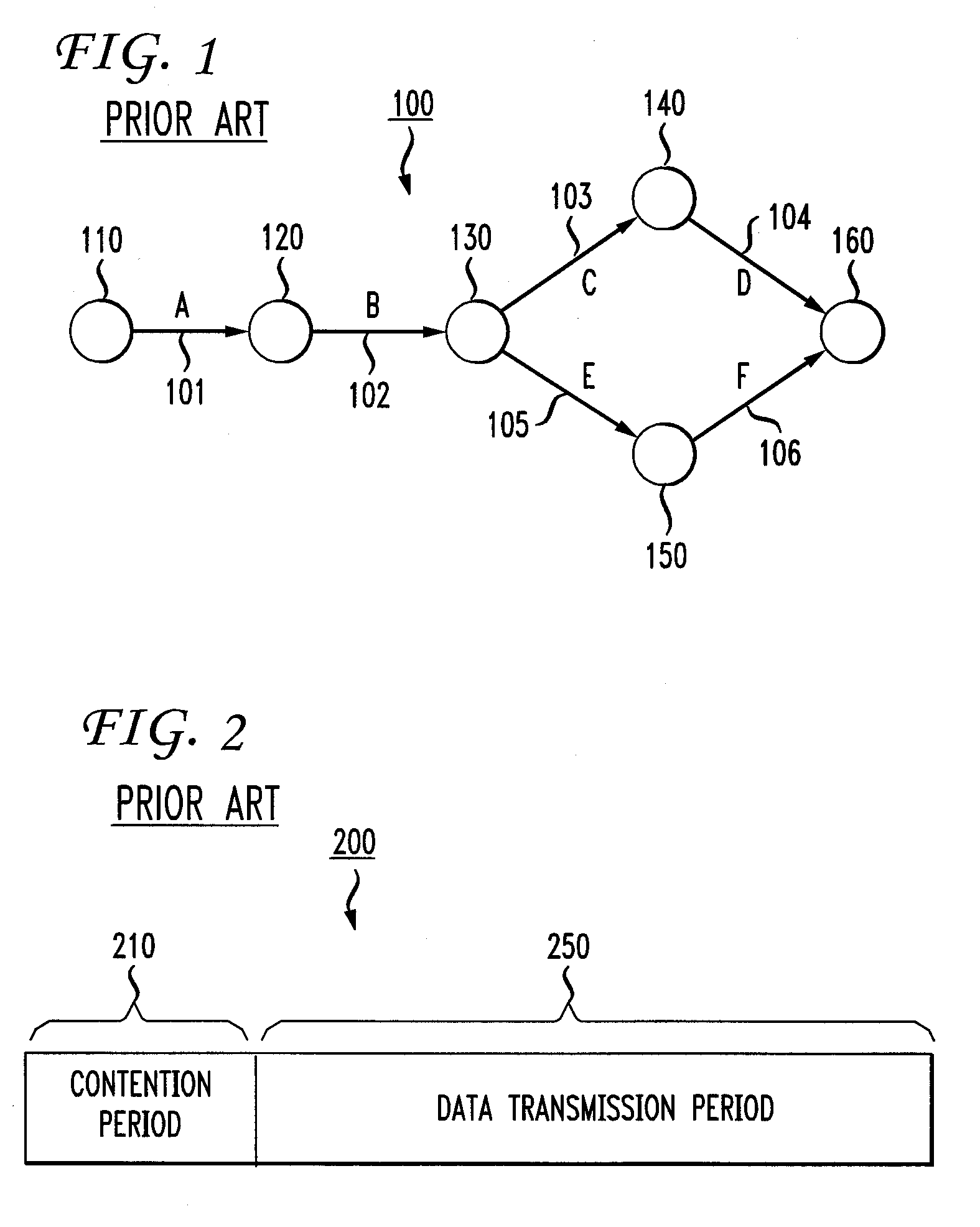
[0014]FIG. 1 is a diagram illustrating a wireless communication network 100 suitable for implementation of an embodiment of the present invention. Wireless network 100 has, illustratively, a plurality of sensor nodes 110-160, each having one or more wireless antennas. Each node is, for example and without limitation, a wireless sensor, such as that discussed above, which gathers and transmits information in a distributed manner. Sensor nodes 110-160 are illustratively arranged in an ad hoc network linked together via illustrative network links 101-106, also denoted as links A-F. As is well known, an ad hoc network is a network in which nodes in the network directly discover and communicate in a peer-to-peer fashion without involving a central access point. In such a network, sensor nodes 110-160 transmit information from one sensor node to another via links 101-106 and are capable of autonomously synchronizing their activities.

[0015]FIG. 2 shows one illustrative embodiment of how s...


PUM


Abstract

A method and apparatus for distributed routing at the network layer of a network is disclosed that integrates contention resolution properties from the MAC layer. In one embodiment, an energy constraint is used in routing at the network layer of a network to determine a first parameter representing the optimal maximum lifetime of a sensor network. If a network link for a transmission is idle, the node may then contend at the MAC layer of the network for a transmission slot across that link. During this contention period, each node is assigned a penalty parameter that is used to represent the probability of a transmission colliding with another transmission across a link in a contention region. As a result of this contention period, network traffic is transmitted from sensor nodes.

Description

[0001] This application claims the benefit of U.S. Provisional Application No. 60 / 717,211, filed Sep. 15, 2005, which is hereby incorporated herein by reference.BACKGROUND OF THE INVENTION [0002] The present invention relates generally to medium access control in communication networks. [0003] Sensor networks are used in many different applications such as, for example, habitat monitoring, location tracking and inventory management. Such networks are typically characterized by hundreds or thousands of individual sensors located at sensor nodes distributed over a desired area. The sensors in a sensor network are typically able to communicate, for example via wired or wireless communications methods, to other sensors and one or more monitoring nodes in the network. A monitoring node is a node that collects and processes data received from the sensor nodes and is, typically more robust than a sensor node. Each sensor is able to detect at least one characteristic of its surroundings by ...

Claims


Application Information

Patent Timeline
Patent Type & Authority Applications(United States)
IPC IPC(8): H04L12/413H04L12/43
CPCH04L12/413H04W40/10H04W52/0219H04W84/18H04W52/0216H04W74/0808Y02D30/70
Inventor KIM, SEUNG-JUNWANG, XIAODONGMADIHIAN, MOHAMMAD
Owner NEC LAB AMERICA
Why Eureka
Try Eureka