
Gear pattern inspection system

a technology of gear pattern and inspection system, applied in the direction of image enhancement, structural/machine measurement, instruments, etc., can solve the problem of substantial bare metal where contact occurred

Inactive Publication Date: 2007-03-15
CASKEY GREGORY T +1
View PDF6 Cites 40 Cited by
  • Summary
  • Abstract
  • Description
  • Claims
  • Application Information

AI Technical Summary

Benefits of technology

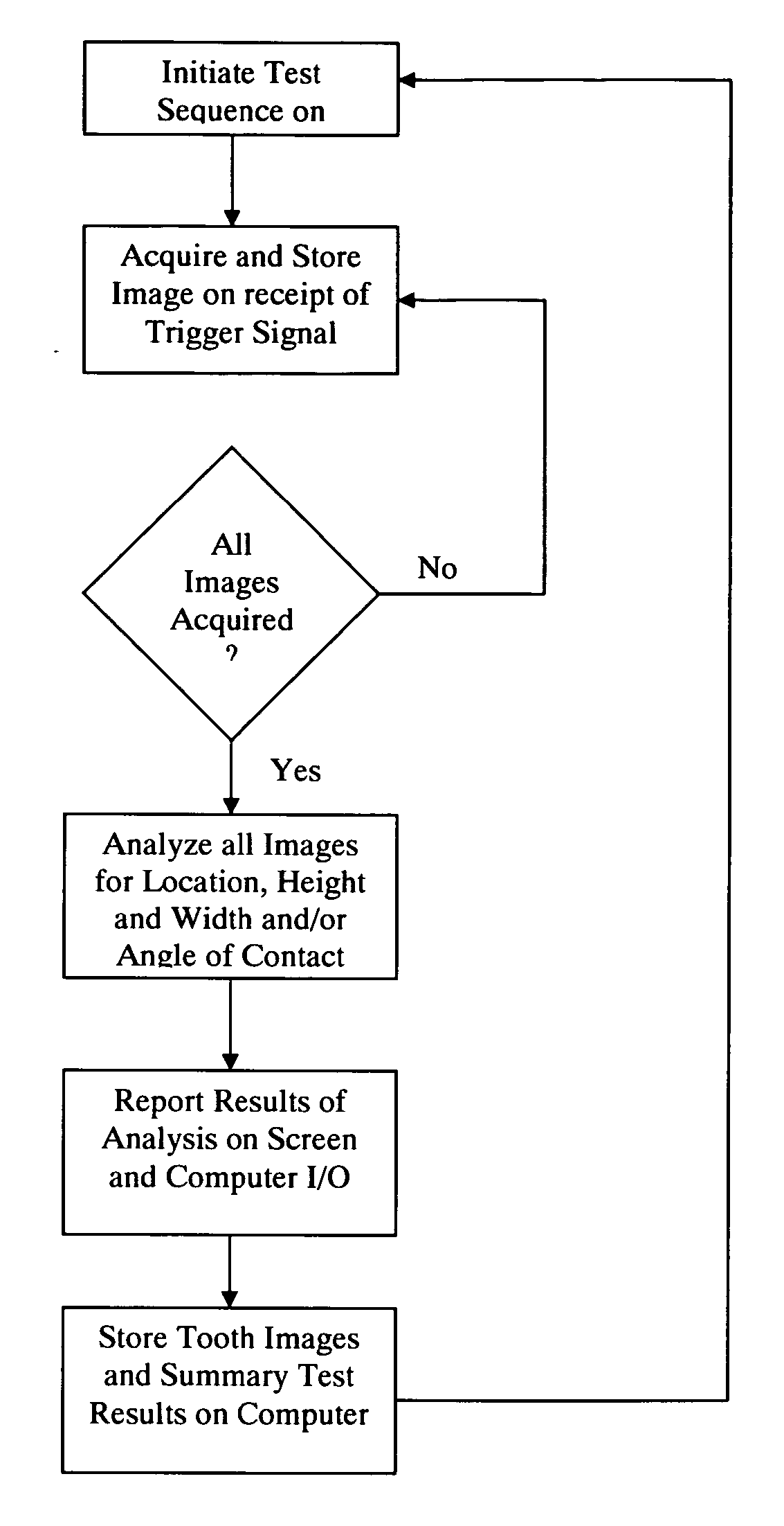
[0022] Accordingly, the apparatus and method of the present invention mimics the same steps a human inspector would do to the extent possible, by using an imaging device, such as a color camera and lighting, such as strobe lighting, a processor, such as a PC type computer, and application software. After spinning the gears for a period of time to produce the pattern where gears were in contact, the gear is spun at a rate commensurate with the imaging system's ability to record images of each gear tooth. Since each gear tooth has two flanks, two views must be recorded. The images are then analyzed via specialized methods to evaluate those characteristics believed important by gear manufacturers. These characteristics may include the centering of contact areas on

Problems solved by technology

Surfaces that contact during spinning push aside or otherwise wear the colorant-laced liquid leaving substantially bare metal where contact occurred.
At production rates, this is a quick judgement of experienced persons, and is therefore subject to all the problems faced by people when involved in a tedious, subjective, repetitive and fast-paced operation.

Method used


Image

  • Gear pattern inspection system
  • Gear pattern inspection system
  • Gear pattern inspection system

Examples


Embodiment Construction

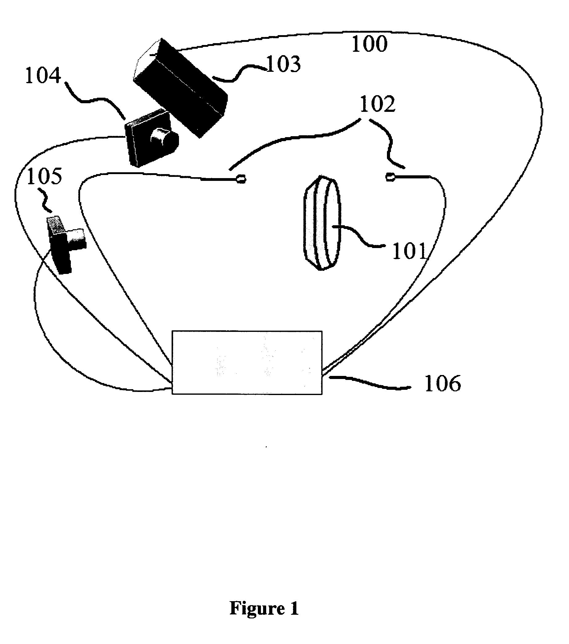
[0030] Referring to FIG. 1, the numeral 100 generally designates a gear inspection apparatus of the present invention. Gear inspection apparatus 100 includes an imaging system for inspecting a gear 101, such as a spiral bevel or other types of gears, and a means for rotating the gear while inspecting the gear. For example, suitable means for rotating the gear include another gear, including a motor gear, a rotating shaft, a robotic arm, or a rotating table or the like. The imaging system includes one or more imaging devices 104, 105, such as cameras, which are used to collect or gather images of the gear's teeth, and a controller 106. In the illustrated embodiment, the imaging system includes a pair of imaging devices 104, 105, for gathering images from both flanks of the gear tooth.

[0031] Controller 106 is in communication with imaging devices 104, and 105 and is configured to collect the images from the imaging devices and further process the images in a manner described in more ...


PUM


Abstract

A method and apparatus for evaluating gears includes an imaging system that provides a non-contact method of evaluating gear meshing using technology that is quick, robust, and provides information not available at production rates from human inspection. The method and apparatus includes one or more imaging devices, illumination, and a computer program to rapidly evaluate the quality of gear set meshing, and which anticipates the move to three-dimensional imaging to permit upstream evaluation of gear quality prior to mating.

Description

CROSS-REFERENCE TO RELATED APPLICATION [0001] This application claims priority from U.S. Pat. application Ser. No. 60 / 716,814, filed Sep. 14, 2005, entitled GEAR PATTERN INSPECTION SYSTEM, which is incorporated by reference herein in its entirety.TECHNICAL FIELD AND BACKGROUND OF THE INVENTION [0002] This invention relates to a common problem among those who produce gear sets. [0003] Spiral bevel, hypoid and other similar gears are used in, for example, power train units in automobiles, trucks and other transportation applications. They are also used on farm machinery, manufacturing machinery, heavy equipment drive trains and in aerospace and various other forms of machinery where power is transmitted through gears. One particular example is their use in transmissions and differentials of cars, trucks, busses and the like. For differentials, these gears are usually mated in pairs of a ring gear and a pinion gear, for example. The pinion gear transmits power to the ring gear, which i...

Claims


Application Information

Patent Timeline
IPC IPC(8): G06K9/00
CPCG01M13/021G06T2207/30164G06T7/0004G01N21/88
Inventor CASKEY, GREGORY T.DEGRAAF, ROLAND E.
Owner CASKEY GREGORY T
Learn More