Golf Glove

Inactive Publication Date: 2007-03-22
HILLERICH & BRADSBY
View PDF100 Cites 32 Cited by
  • Summary
  • Abstract
  • Description
  • Claims
  • Application Information

AI Technical Summary

Benefits of technology

[0007] In the development of gloves, several key elements are utilized in the design. First, on the dorsal side of the glove, the motion zones are determined by the center axis of rotation of the individual thumb, finger, hand, and wrist joints. These motion zones have been applied to specific joint locations for the particular uses of a designed glove. This helps the flexibility of the glove in relationship to its use. As such, the motion zones are selected in various combinations or even individually depending on the specific task or function of the glove.
[0008] Secondly, on the palm side of the glove there are additional motion zones. Again, these motion zones, which also function to decrease glove impedance and improve the breath-ability of the glove, are located specifically in relationship to the center axis of rotation of the finger joints.

Problems solved by technology

Secondly, on the palm side of the glove there are additional motion zones.

Method used


Image

  • Golf Glove
  • Golf Glove
  • Golf Glove

Examples


Embodiment Construction

A. Batting Glove

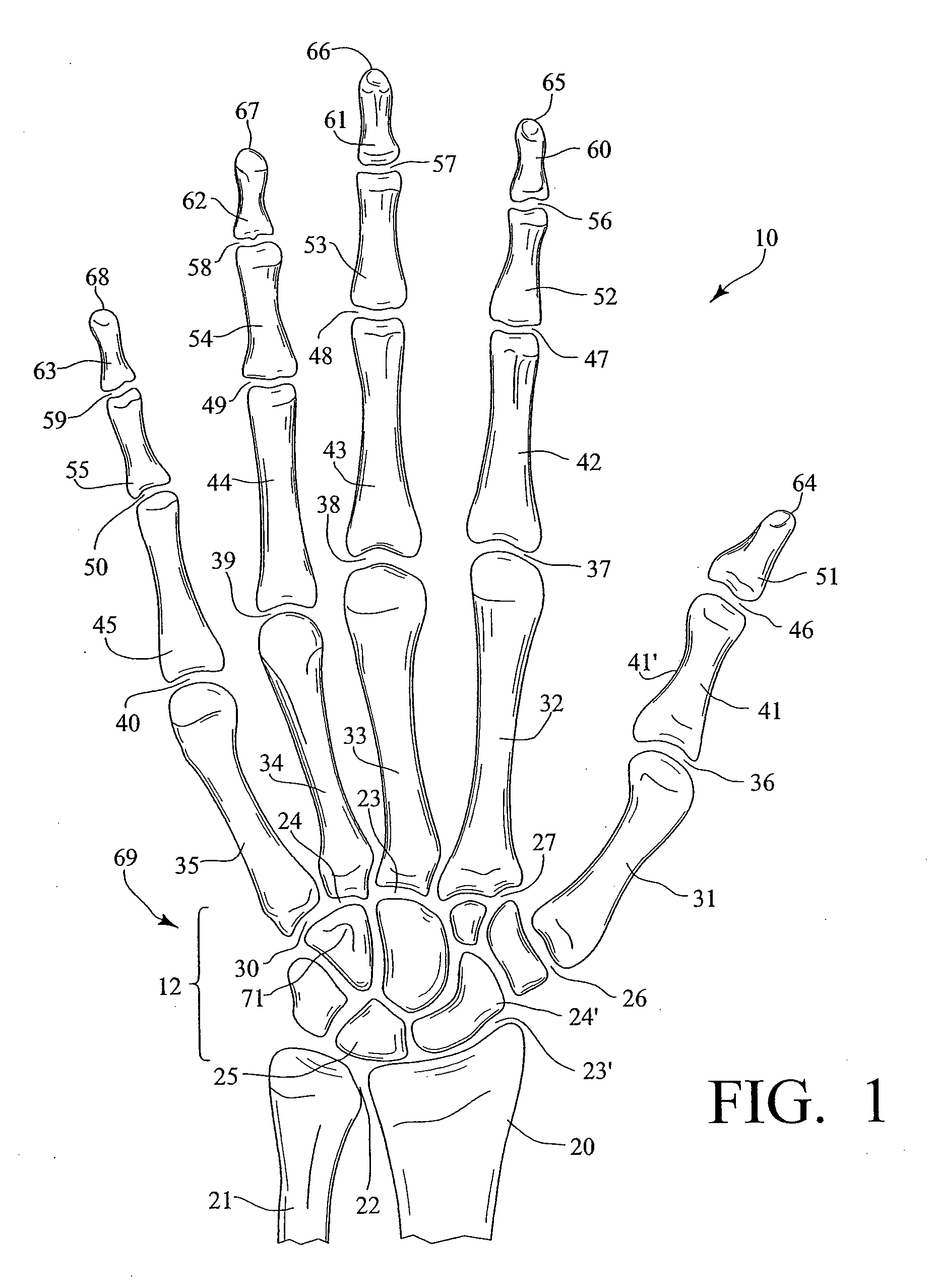
[0049]FIG. 1 is a schematic anatomical view of the bones of a right human hand 10 looking at a palm 18 side. Shown are the radius 20, ulna 21, radiocarpal joint (RC) 23′, distal radio ulnar joint (DRUJ) 22, wrist 12, thumb 64, index finger 65, long finger 66, ring finger 67, and small finger 68. The carpus 69 comprises eight carpal bones, seven of which are shown in FIG. 1 and includes the hamate bone 71 with its hook-like protrusion, the scaphoid 24′ and the lunate 25.

[0050] The thumb 64 is comprised of the distal phalanx 51, the interphalangeal joint (IP) 46, proximal phalanx 41, diaphysis of proximal phalanx 41′, metacarpalphalangeal joint (MCP) 36, metacarpal 31, and carpometacarpal joint (CMC) 26.

[0051] The index finger 65 is comprised of the distal phalanx 60, distal interphalangeal joint (DIP) 56, middle phalanx 52, proximal interphalangeal joint (PIP) 47, proximal phalanx 42, metacarpalphalangeal joint (MCP) 37, metacarpal 32, and carpometacarpal joint (CMC...


PUM


Abstract

A golf glove is provided with a plurality of finger stalls having an upper portion and a lower portion wherein the lower portion includes a protective covering with a moisture absorbing material for location below the center axis of rotation of the proximal interphalangeal joint and above the center axis of rotation of the proximal interphalangeal joints. The lower portion may also include an elastic material covering the center axis of rotation of the proximal interphalangeal joints.

Description

CROSS REFERENCE TO RELATED APPLICATIONS [0001] This application is a continuation-in-part of and claims priority to and benefit from, currently pending U.S. patent application Ser. No. 11 / 243,311 filed Oct. 4, 2005, which is a continuation-in-part of U.S. patent application Ser. No. 10 / 670,859 filed Sep. 25, 2003, now U.S. Pat. No. 7,000,256 issued Feb. 21, 2006, which is a continuation-in-part of patent application Ser. No. 10 / 001,325 filed Oct. 25, 2001, now U.S. Pat. No. 6,701,530 issued Mar. 9, 2004, which is a continuation-in-part of and claims priority to and benefit from U.S. patent application Ser. No. 09 / 867,084 filed May 29, 2001, now U.S. Pat. No. 6,389,601 issued on May 21, 2002, which is a continuation of and claims priority to and benefit from U.S. patent application Ser. No. 09 / 491,742 filed Jan. 27, 2000 now U.S. Pat. No. 6,253,382 issued on Jul. 3, 2001. BACKGROUND OF THE INVENTION [0002] 1. Field of the Invention [0003] This invention relates to gloves for the huma...

Claims


Application Information

Patent Timeline
IPC IPC(8): A41D19/00
CPCA41D19/00A41D19/015A63B71/143A63B71/146A63B2243/0045A63B2243/0004A63B2243/0008A63B2243/0029A63B2209/10A63B2102/24A63B2102/32A63B2102/18A63B2102/182A41D19/01523A41D19/01547A41D19/01576A41D19/01582A41D31/12
Inventor KLEINERT, JAMES M.
Owner HILLERICH & BRADSBY
Why Eureka
Try Eureka