Pneumatically actuated disk brake with electromotive adjusting devices and method for controlling the disk brake

Inactive Publication Date: 2007-03-22
KNORR-BREMSE SYST FUER NUTZFAHRZEUGE GMBH
View PDF4 Cites 8 Cited by
  • Summary
  • Abstract
  • Description
  • Claims
  • Application Information

AI Technical Summary

Benefits of technology

[0015] In this way, brakings are not impeded and yet the rubbing effects which arise during travel, resulting in higher wear and fuel consumption, are minimized and the prospect of “intelligent” adjustment of the play, including “intelligent” play function, is optimized. As a result of the prospect of minimizing the fuel consumption, this disk brake will inevitably in future be the brake of choice, in particular in an additionally space-saving design as a fixed-caliper brake with intelligent, since electric

Problems solved by technology

The contact between brake disk and brake pad is released by the vibrations which are usually generated during driving, or due to a so-called wobble of the brake disk, which is undesirable per se.
The further contact between the brake pads and the brake disk following the release of the brake application device gives rise to an additional wear of both the brake disk and the brake pads, which results in a reduced service life for the wearing parts, with the corresponding cost disadvantages in terms of spare parts procurement and installation and removal.
As a result of a somewhat longer contact of the brake pads against the brake disk, the brake temperatures are somewhat increased, which can likewise have an adverse effect on service life.
Apart from t

Method used


Image

  • Pneumatically actuated disk brake with electromotive adjusting devices and method for controlling the disk brake
  • Pneumatically actuated disk brake with electromotive adjusting devices and method for controlling the disk brake
  • Pneumatically actuated disk brake with electromotive adjusting devices and method for controlling the disk brake

Examples


Embodiment Construction

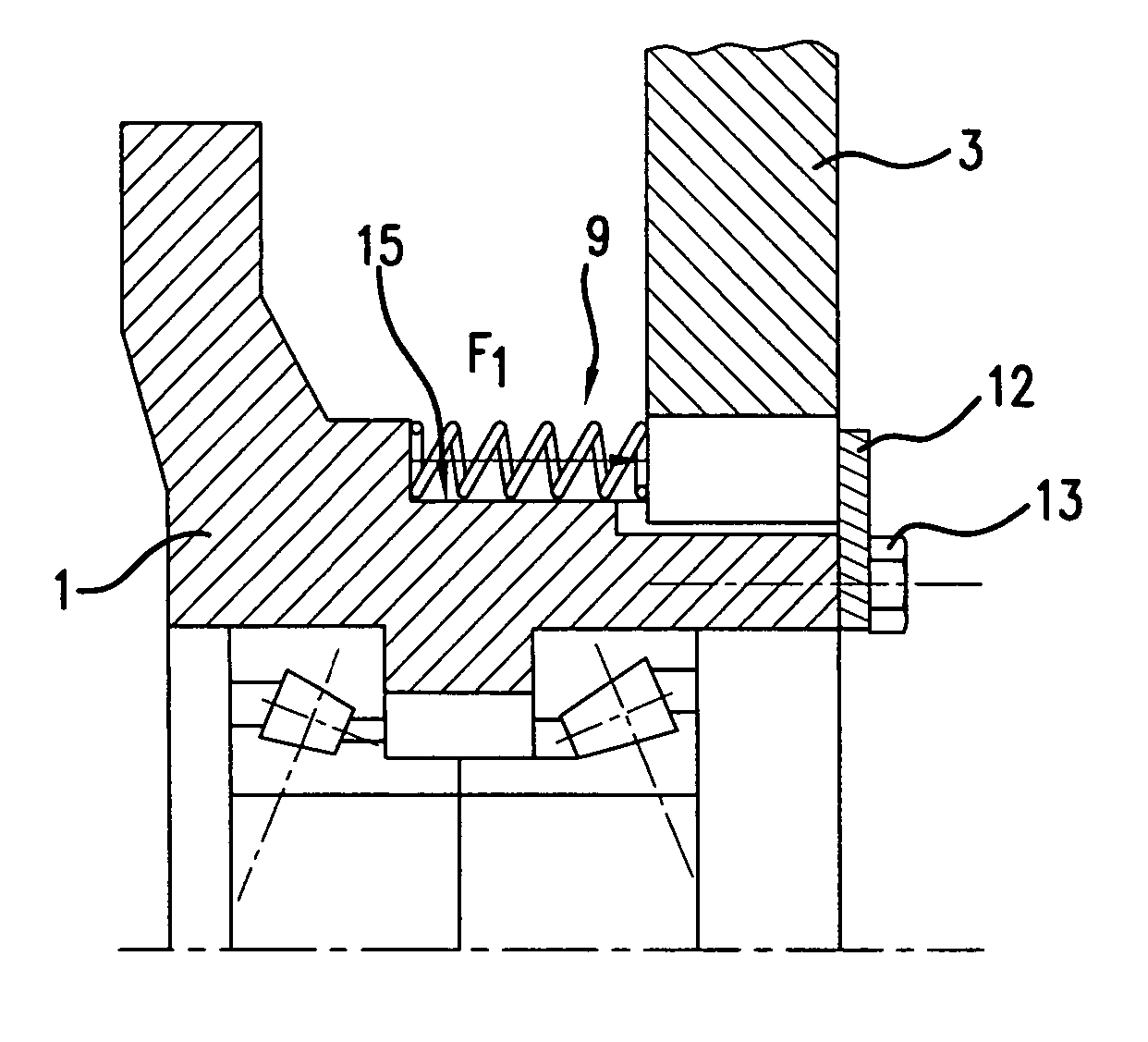
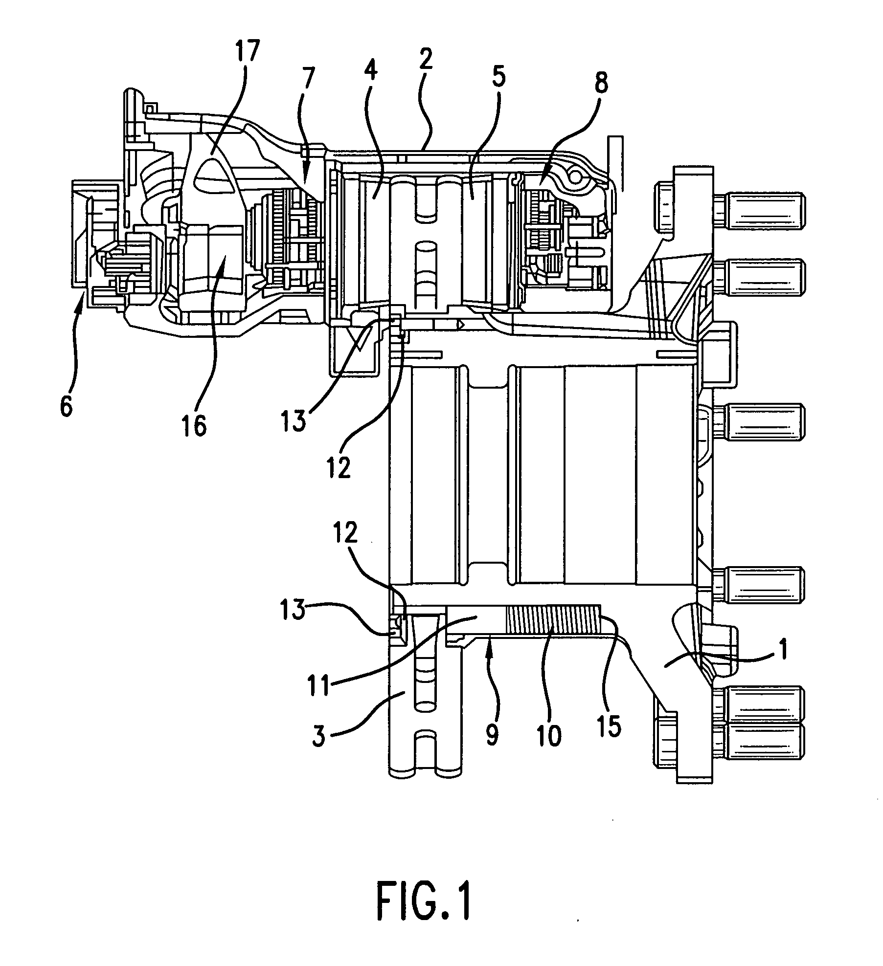
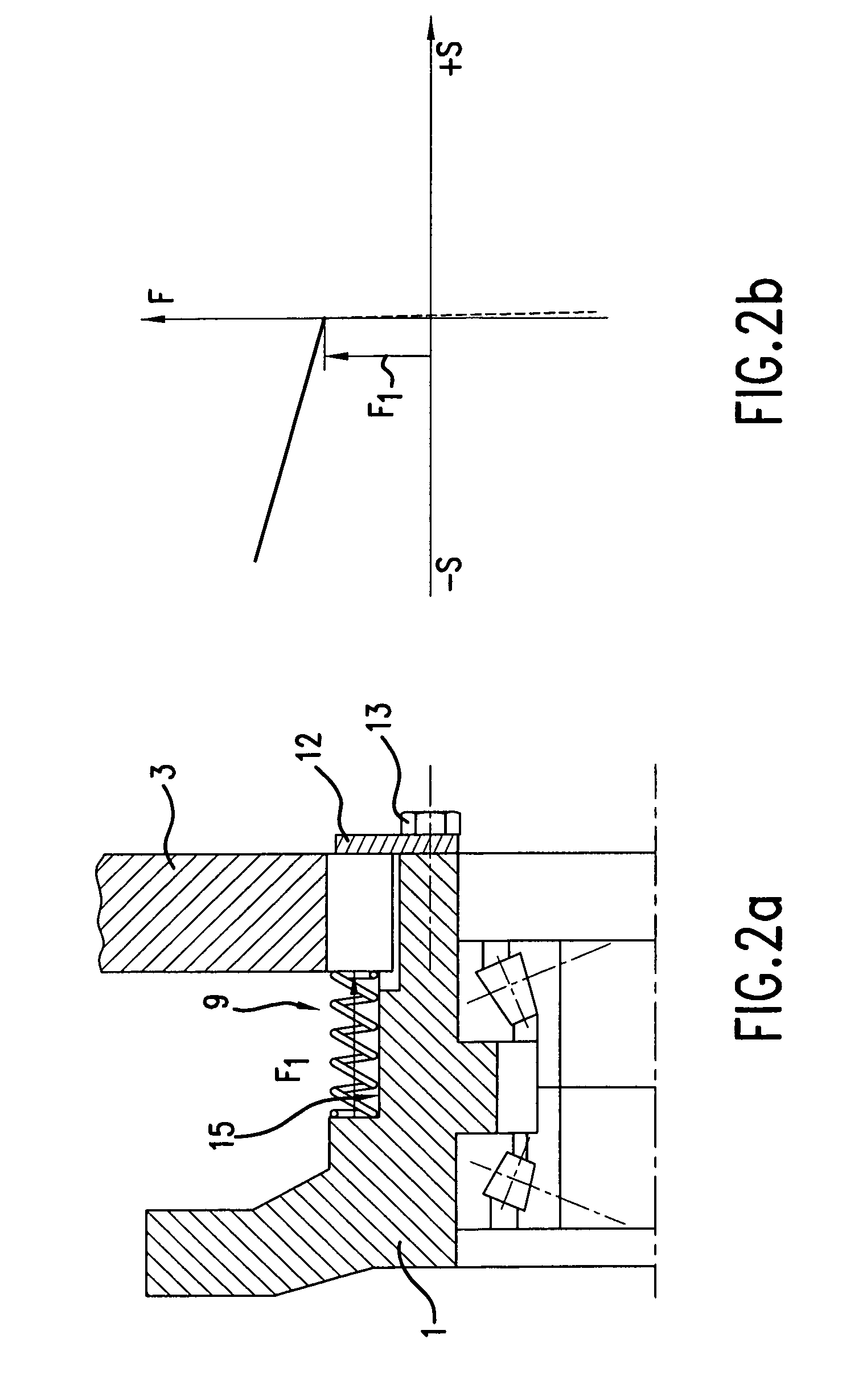
[0043] In FIG. 1, a brake disk for commercial vehicles, which is here configured, by way of example, as a fixed-caliper brake, is represented, which has a brake caliper 2 which is configured as a fixed caliper and reaches over a brake disk 3, which is disposed in an axially displaceable and torsionally secure manner on a vehicle part configured as an axle flange 1. The fixed caliper 2 is fixed immovably on the axle flange 1.

[0044] In the fixed caliper 2 there is disposed a brake application device 16, actuable by a piston rod of a brake cylinder and having an eccentrically mounted swivel lever 17, which brake application device is designed and constructed such that, when the swivel lever 17 is pivoted, pressure pieces (here not recognizable in detail) on this side of the brake disk 3 (referred to as the brake application side) are displaced parallel to the brake disk axis and press a brake shoe 4 disposed on the brake application side against the brake disk 3, which latter, if the ...


PUM


Abstract

An electro mechanical or pneumatically actuated disk brake, in particular for a utility vehicle, includes a brake caliper or saddle and a brake disk. The brake saddle overlaps the brake disk at least in sections of the outer periphery thereof. The disk brake also includes a tensioning device which is entirely or partially inserted into the brake saddle. The tensioning device is used to produce a tensioning movement between the brake linings and the brake disk. The disk brake further includes at least one, and preferably several, adjusting devices. The brake disk and/or the brake saddle are arranged on a stop with elastic pre-tension when the brake is in a release state. Braking is determined by a control method in a sensor-free manner during adjustment.

Description

[0001] This application is a continuation of international application no. PCT / EP2004 / 014009, filed Dec. 9, 2004, the entire disclosure of which is incorporated herein by reference. [0002] This application also claims the priority of German application 103 57 374.7, filed Dec. 9, 2003.BACKGROUND AND SUMMARY OF THE INVENTION [0003] The present invention relates to a pneumatically actuated disk brake with electromotively driven adjusting devices and a method for controlling the disk brake. [0004] In known compressed-air-actuated disk brakes, a braking operation is effected by an actuation of the brake application device, for example by movement of a piston rod of a pneumatically operating brake cylinder, by which movement a connected brake pad is pressed against the brake disk. Depending on whether the disk brake is designed as a fixed-caliper brake or as a sliding-caliper or hinged-caliper brake (or as a combination of these brake types), the brake disk is pushed toward the further b...

Claims


Application Information

Patent Timeline
IPC IPC(8): F16D55/02F16D65/12F16D65/14
CPCF16D65/12F16D65/18F16D2055/0062F16D2065/1348F16D2127/02F16D2065/1396F16D2065/386F16D2066/006F16D2121/14F16D2065/1368
Inventor LEINUNG, ANDREASLEISTER, MARKUSBAUMGARTNER, JOHANNPAHLE, WOLFGANG
Owner KNORR-BREMSE SYST FUER NUTZFAHRZEUGE GMBH
Why Eureka
Try Eureka