Bi-metal disc brake rotor and method of manufacturing

a technology of brake disc and metal disc, which is applied in the direction of brake disc, manufacturing tools, mechanical equipment, etc., can solve the problems of brake squeal countermeasures and undesirable brake squeal, and achieve the effect of preventing corrosion-causing exterior elements

Inactive Publication Date: 2007-03-22
GM GLOBAL TECH OPERATIONS LLC
View PDF81 Cites 77 Cited by
  • Summary
  • Abstract
  • Description
  • Claims
  • Application Information

AI Technical Summary

Benefits of technology

[0007] The invention provides a method for manufacturing a friction damped disc brake rotor, including the steps of: (A) providing a ceramic coating or other suitable coating on an insert, wherein the insert has a body with tabs extending therefrom to hold the insert in a desired position within a mold; (B) washing the ceramic coating off of the tabs; (C) positioning the insert into the mold; and (D) casting a rotor cheek of the disc brake rotor in the mold

Problems solved by technology

Brake squeal can be undesirably generated at the brake corner when braking occurs.
And unfortunately, brake corners for performance motor vehicles, or those motor vehicles with hi

Method used


Image

  • Bi-metal disc brake rotor and method of manufacturing
  • Bi-metal disc brake rotor and method of manufacturing
  • Bi-metal disc brake rotor and method of manufacturing

Examples


Embodiment Construction

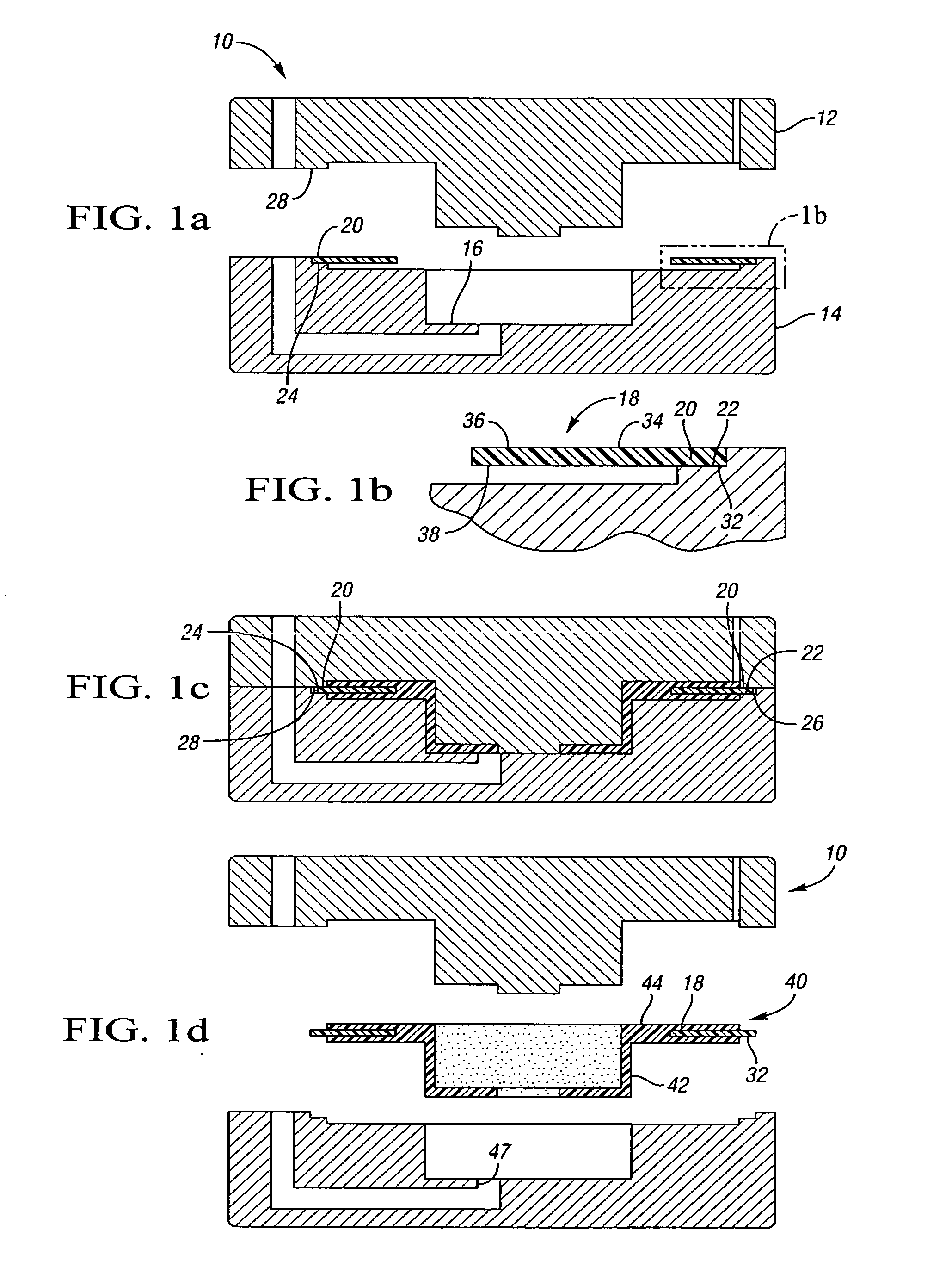
[0021] Referring to FIG. 1a, a mold 10 is accordance with the invention having upper and lower mold halves 12, 14 which form a cavity 16 therebetween for casting a friction damped disk brake rotor in accordance with the invention. FIG. 1b shows an insert 18 which is pre-positioned within the mold 10 and having tabs 20 which rest on cutout portions 22, 24 of the lower mold half 14. As shown in FIG. 1c, when the upper and lower mold halves 12, 14 are closed together, the tabs 20 are supported between the cutout portions 22, 24 of the lower mold half 14 and the lands 26, 28, respectively of the upper mold half 12.

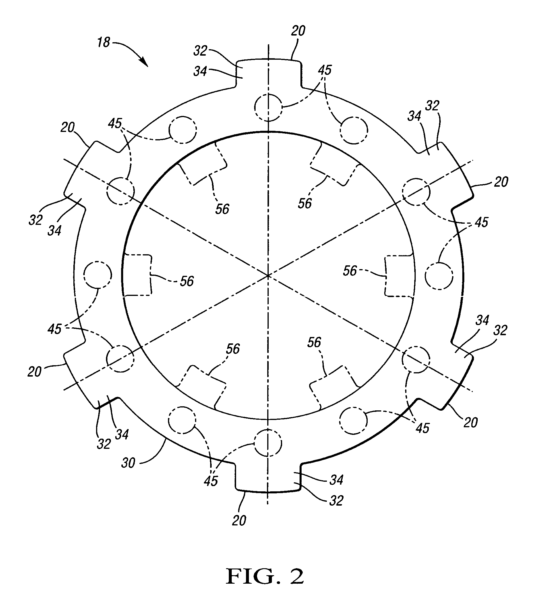
[0022] Referring to FIG. 2, the insert 18 is shown in plan view. As shown, the insert 18 has a generally annular body 30 with tabs 20 extending therefrom. Each tab includes a distal portion 32 and a proximal portion 34. The distal portion 32 is trapped between the cutout portions 22, 24 and the lands 26, 28, respectively, shown in FIG. 1c, while the proximal portion 34 of eac...


PUM

PropertyMeasurementUnit
Thicknessaaaaaaaaaa
Thicknessaaaaaaaaaa
Thicknessaaaaaaaaaa

Abstract

The invention provides a method for manufacturing a friction damped disc brake rotor, including the steps of: (A) providing a ceramic coating on an insert, wherein the insert has a body with tabs extending therefrom to hold the insert in a desired position within a mold; (B) washing the ceramic coating off of the tabs; (C) positioning the insert into the mold; and (D) casting a rotor cheek of the disc brake rotor in the mold around the insert such that a portion of each tab is bonded with the rotor cheek, and such that the coating is substantially non-bonded with the rotor cheek so that the coating provides a proper interfacial boundary between the body and the cheek for damping, and the at least partial bonding of each tab with the rotor cheek prevents corrosion-causing exterior elements from reaching the interfacial boundary when the friction damped disc brake rotor is in use.

Description

CROSS-REFERENCE TO RELATED APPLICATION [0001] This application claims the benefit of U.S. Provisional Application No. 60 / 718,579, filed Sep. 19, 2005.TECHNICAL FIELD [0002] The present invention relates to a bi-metal disc brake rotor and a method of manufacturing bi-metal brake disc rotors in which an insert is cast into the brake rotor in a manner to provide improved noise damping without subjecting the rotor to corrosion. BACKGROUND OF THE INVENTION [0003] Motor vehicle disc brake systems utilize a disc brake rotor at each respective wheel, wherein the disc brake rotor typically includes a rotor hat for connecting to an axle hub of a rotatable axle of the motor vehicle, and at least one annular rotor cheek connected to the rotor hat, wherein the at least one rotor cheek has a pair of mutually opposed braking surfaces onto which brake pads are selectively applied when braking is desired. Typically, the rotor cheek configuration may be solid, in which case a single rotor cheek has o...

Claims


Application Information

Patent Timeline
IPC IPC(8): F16D65/12
CPCB22D19/00Y10T29/49885F16D65/12F16D2065/1316F16D2065/132F16D2065/1344F16D2200/0013F16D2200/0021F16D2250/00F16D2250/0015F16D2250/0092Y10T29/49982Y10T29/49888Y10T29/49988Y10T29/49984F16D65/0006
Inventor HANNA, MICHAEL D.SCHROTH, JAMES G.HAMMAR, RICHARD H.DESSOUKI, OMAR S.LOWE, BRENT D.RIEFE, MARK T.SHORT, JEREMY W.SCHERTZER, ANDREW
Owner GM GLOBAL TECH OPERATIONS LLC
Why Eureka
Try Eureka