Device and method for sensing a position of a probe

Inactive Publication Date: 2007-03-22
GLOBALFOUNDRIES INC
View PDF4 Cites 13 Cited by
  • Summary
  • Abstract
  • Description
  • Claims
  • Application Information

AI Technical Summary

Benefits of technology

[0029] The bridge type oscillator provides superior stability and phase noise performance.
[0030] According to yet another embodiment of the first aspect of the invention, wherein each one of the above-described relaxation oscillator circuit, LC-resonating circuit, RC delay line oscillator and bridge-type oscillator further comprises a phase-locking unit for synchronising the circuit to an external clock. In this way, position information contained in a control signal may be used for adjusting the frequency of the circuit

Problems solved by technology

This may render it unnecessary to measure small analog signals on an absolute scale.
Additionally, this may further substantially reduce manufacturing tolerance-related sensitivit

Method used


Image

  • Device and method for sensing a position of a probe
  • Device and method for sensing a position of a probe
  • Device and method for sensing a position of a probe

Examples


Example

FIRST EMBODIMENT

[0079] A first embodiment of the present invention comprises a relaxation oscillator circuit, which is shown in FIG. 8. It is, during operation, electrically connected to the heater element HE of the respective probe 6. It is arranged in the control and information processing unit 12. It comprises voltage sources being designed for generating a first and a second bias voltage potential V_b1, V_b2, respectively.

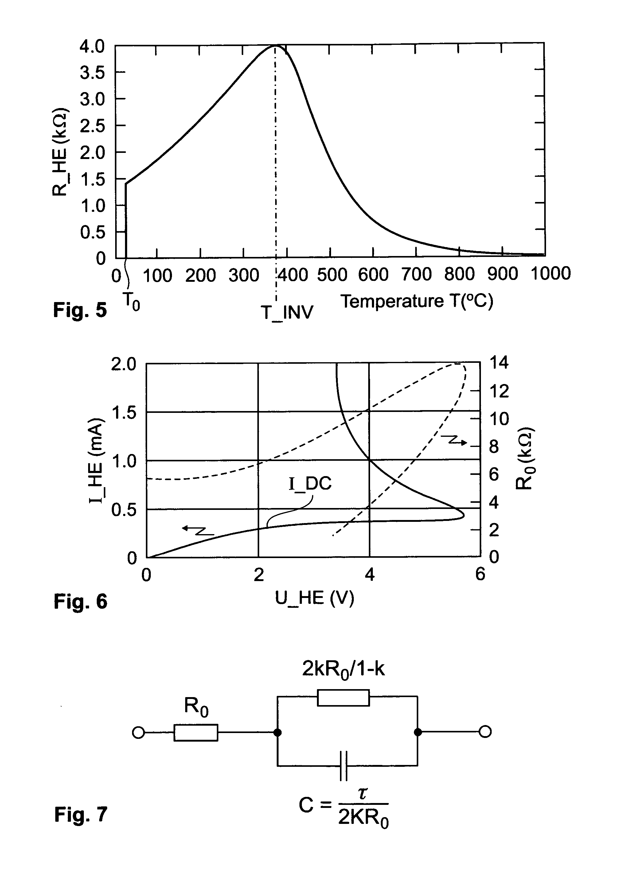
[0080] The heater element HE may be represented by its electrical equivalent circuit according to FIG. 7. When operating an electrical heater in the area of the plateau region of the current / voltage interrelationship curve I_DC, the parallel resistance to the electrical capacitance C_HE of the heater element HE may be assumed to be significantly greater than the operating point electrical resistance R_0. It is to be noted that the operating point may be represented by a current source being arranged in a parallel fashion to the equivalent circuit according to...

Example

SECOND EMBODIMENT

[0093] A second embodiment of an electronic circuit enabling the sensing of the position of the heater element HE relative to the storage medium 2 comprises an LC-resonating circuit and is shown in FIG. 10. During operation of the circuit, the heater element HE is electrically connected on one side to the current / voltage converter 40 and on the other hand the heater element is connected to an output of a feedback amplifier 50. The heater element HE is arranged electrically in parallel to an inductance L.

[0094] The output of the feedback amplifier 50 has a signal that is representative of the resonance frequency f_RES_LC of the LC-resonating circuit. A Q factor will be of order unity for resonance frequencies comparable to 1 / tau_el, which renders this circuit practical preferably for low frequency applications (f_RES_LC0).

[0095] In this embodiment, the resonant frequency f_RES_LC is proportional to the electrical relaxation time tau_el and, hence, the thermal rela...

Example

THIRD EMBODIMENT

[0096] A third embodiment comprises a RC delay line oscillator and is shown in FIG. 11. The electrical resistors R1 and R2 and the capacitors C1 and C2 are preferably dimensioned in the order of the operating point electrical resistance R_0 and respectively the electrical capacitance C_HE of the heater element HE. More preferably, they match the respective operating point electrical resistance R_0 and respectively the electrical capacitance C_HE of the heater element HE in a range of at maximum a factor 2 to 3. The advantage is that the resistors R1, R2 and the capacitors C1 and C2 do not have to exactly match the operating point electrical resistance R_0 and / or respectively the electrical capacitance C_HE of the heater element HE in order to obtain a signal that appropriately measures the thermal relaxation time tau. The RC delay line oscillator further comprises the current / voltage converter 40 and the feedback amplifier 50.

[0097] The output of the feedback ampli...


PUM


Abstract

A device for sensing a position of a probe relative to a reference medium, the probe comprising a heater element with a temperature dependent electrical resistance and being adapted to determine probe position by measuring a parameter associated to a thermal relaxation time of the heater element.

Description

TECHNICAL FIELD [0001] The present invention relates to a method and a device for sensing a position of a probe relative to a reference medium. BACKGROUND OF THE INVENTION [0002] In the field of the present invention, micro electromechanical systems (MEMs) are included being the technology of mechanical components on the micrometer size, which includes three dimensional lithographic features of various geometries. They are typically manufactured using planar processing similar to semiconductor processes such as surface micromachining and / or bulk micromachining. MEMS are often fabricated using modified silicon fabrication technology, molding and plating, electro-discharge machining and other technologies capable of manufacturing very small devices. The field of the present invention also embraces techniques that use nanometer-sized tips for imaging and investigating the structure of materials down to the atomic scale. Such techniques include scanning tunneling microscopy (STM) and at...

Claims


Application Information

Patent Timeline
IPC IPC(8): G21K7/00
CPCB82Y10/00G11B9/1409G01Q80/00
Inventor DUERIG, URS T.GOTSMANN, BERND W.KNOLL, ARMIN W.
Owner GLOBALFOUNDRIES INC
Why Eureka
Try Eureka