

Two-point frequency modulation apparatus, wireless transmitting apparatus, and wireless receiving apparatus
a frequency modulation and wireless transmission technology, applied in the direction of modulation, digital transmission, pulse automatic control, etc., can solve the problems of deteriorating modulation accuracy, affecting the accuracy of input timing difference adjustment, and widening the pll bandwidth at the risk of deteriorating noise characteristics, etc., to achieve the effect of improving modulation accuracy
- Summary
- Abstract
- Description
- Claims
- Application Information
AI Technical Summary
Benefits of technology
Problems solved by technology
Method used
Image

Examples
embodiment 1
[Structure of Two-Point Frequency Modulation Apparatus]
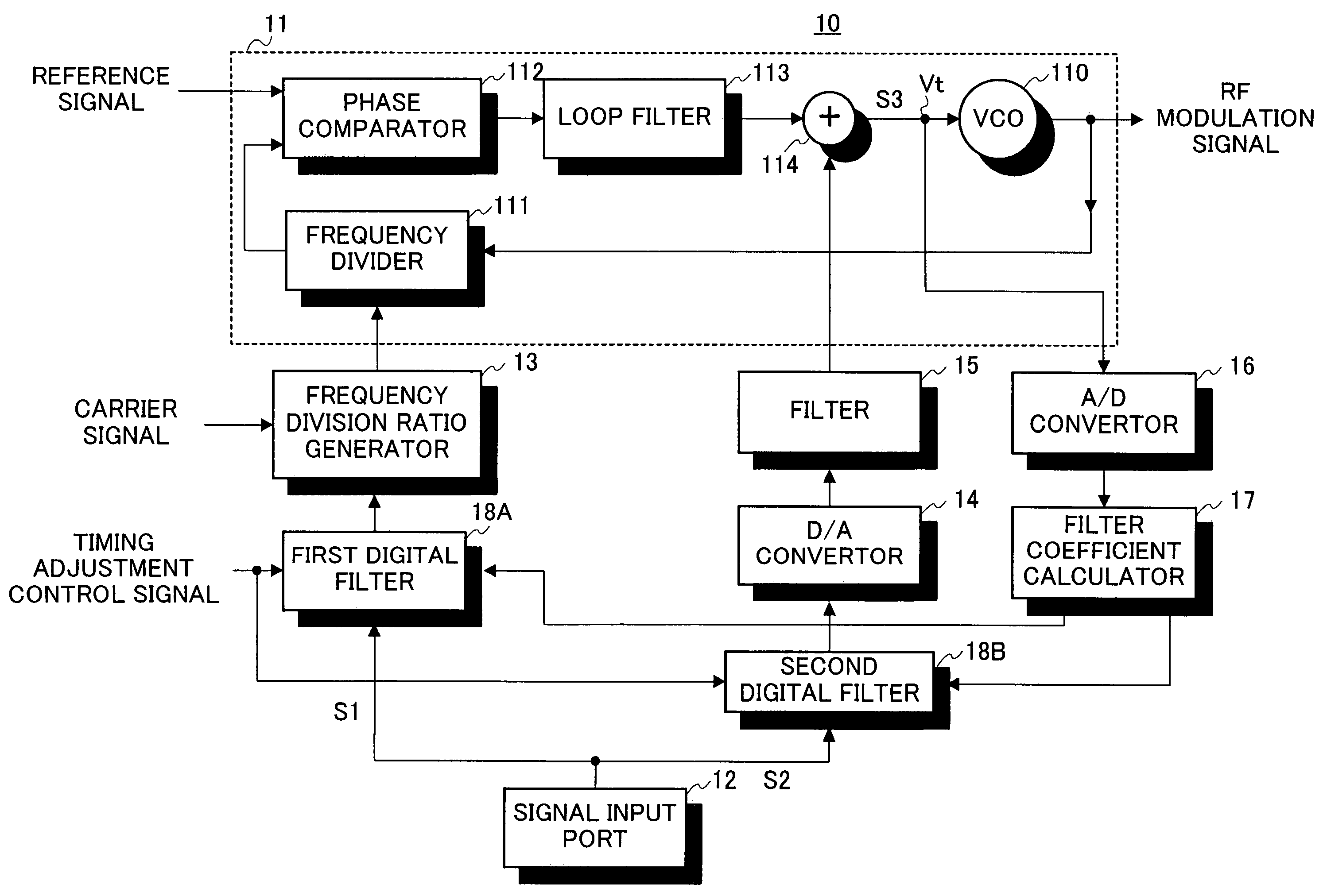
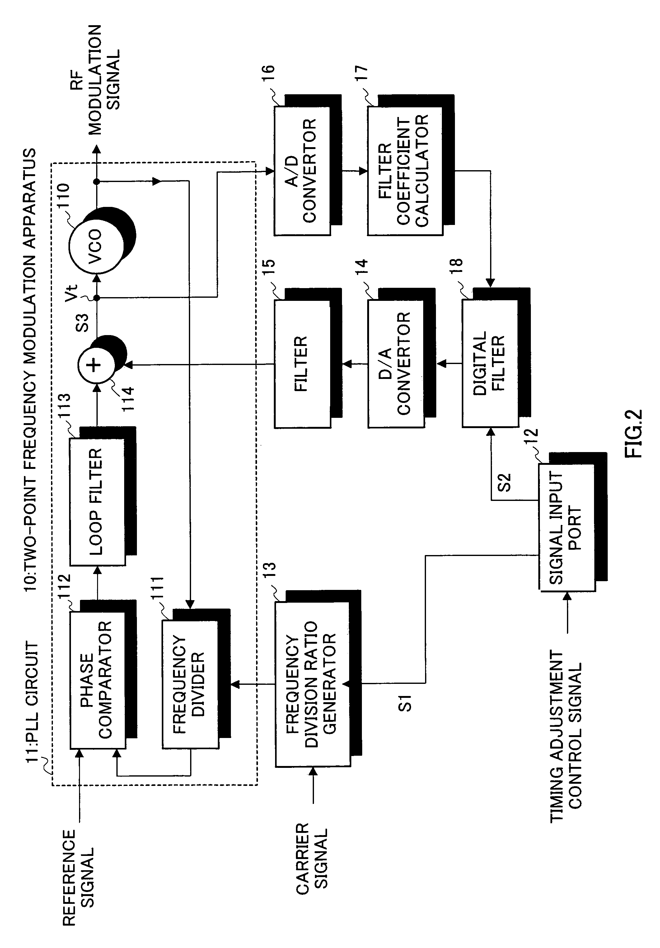
[0038]As shown in FIG. 2, two-point frequency modulation apparatus 10 according to Embodiments 1 of the present invention has PLL circuit 11, which includes voltage controlled oscillator (VCO) 110, frequency divider 111, phase comparator 112, and loop filter 113. In addition, two-point frequency modulation apparatus 10 has: a frequency division ratio setter that sets the frequency division ratio in frequency divider 111 based on first digital baseband signal S1 and carrier signal; a signal adder that adds second digital baseband signal S2 to the output signal of loop filter 113; a delay index calculator that calculates the delay index in accordance with the magnitude of change in the amplitude of the composite signal combining the output signal of loop filter 112 and second digital baseband signal S2; and a delay adjustor that shifts the phase of second digital baseband signal S2 in accordance with the delay index and reduces th...
embodiment 2
[0074]A case will be described here with Embodiment 2 of the present invention where, in two-point frequency modulation apparatus 10 of Embodiment 1, the method of inverting digital baseband signals in input timing adjustment mode in two-point modulation is changed.
[0075]As shown in FIG. 13, two-point frequency modulation apparatus 10 according to Embodiment 2 has signal input port 12 that outputs digital baseband signal S1 to frequency division ratio generator 13 and digital filter 18, and digital filter 18 (i.e. delay adjustor) that, in input timing adjustment mode, generate second digital baseband signal S2, which is an inverted version of first digital baseband signal S1, and performs the delay adjustment of this second digital baseband signal S2 by way of phase shift and outputs the result.
[0076]As shown in FIG. 14, this digital filter 18 is fundamentally the same structure as that of digital filter 18 in two-point frequency modulation apparatus 10 according to Embodiment 1, ex...
embodiment 3
[0078]A case will be described here with Embodiment 3 of the present invention where the two-point frequency modulation apparatus of Embodiment 2 does not invert digital baseband signals in input timing adjustment mode.
[0079]As shown in FIG. 15, two-point frequency modulation apparatus 10 according to Embodiment 3 has: signal input port 12, which basically has the same configuration as signal input port 12 of two-point frequency modulation apparatus 10 of Embodiment 2; and digital filter 18 which basically has the same configuration as digital filter 18 in two-point frequency modulation apparatus 10 of Embodiment 1. In this Embodiment, signal input port 12 outputs digital baseband signal S1 to frequency division ratio generator 13 and digital filter 18. In input timing adjustment mode and in normal mode, digital filter 18 generates and outputs second digital baseband signal S2 that is not inverted and that therefore is the same as first digital baseband signal S1.
[0080]Now, in two-p...
PUM
 Abstract
Description
Claims
Application Information