Self-calibrating modulator apparatuses and methods

a self-calibration and modulator technology, applied in simultaneous amplitude and angle modulation, modulation, instruments, etc., can solve the problems of difficult or impossible to comply with communications standards specifications, inability to provide linear response over the entire pm bandwidth, etc., to improve the modulation accuracy and performance of communications systems, improve the modulation accuracy and scaling precision, and improve the effect of modulation accuracy

Inactive Publication Date: 2010-06-29
PANASONIC CORP
View PDF5 Cites 2 Cited by
  • Summary
  • Abstract
  • Description
  • Claims
  • Application Information

AI Technical Summary

Benefits of technology

[0006]The frequency dependent oscillator gain coefficients determined from the calibration process are stored in a look up table (LUT). Following the calibration process, when the self-calibrating modulator apparatus is configured for normal operation, scaling circuitry is employed to scale (or “predistort”) a modulation signal applied to the modulator by the frequency dependent oscillator gain coefficients stored in the LUT. By scaling the modulation signal prior to it being applied to the control input of the controlled oscillator, the frequency dependent nonlinear response of the controlled oscillator is countered and the modulation accuracy of the modulator is thereby improved. To increase the precision of the scaling, the oscillator gain calibration circuit includes an interpolation filter, which may be employed to determine additional oscillator gain coefficients from the frequency dependent oscillator gain coefficients stored in the LUT.
[0007]The self-calibrating methods and apparatuses of the present invention improve the modulation accuracy and performance of communications systems, particularly wideband communications systems. For example, according to one embodiment of the invention, the self-calibrating modulator apparatus is employed in the phase modulation path of a polar modulation transmitter, to improve the modulation accuracy of the transmitter. The self-calibrating methods and apparatuses of the present invention also allow lower-cost controlled oscillators to be used than would otherwise be required, since linearity design requirements and part-to-part performance variation restrictions can be relaxed. Finally, the calibration methods are performed in the field, thereby advantageously avoiding the tedium and expense characteristic of factory calibration.

Problems solved by technology

However, as illustrated in FIG. 2, in wideband applications the VCO 104 is incapable of providing a linear response over the entire PM bandwidth.
The nonlinear response results in distortion of the polar modulation transmitter output signal, making it difficult or impossible to comply with communications standards specifications.

Method used


Image

  • Self-calibrating modulator apparatuses and methods
  • Self-calibrating modulator apparatuses and methods
  • Self-calibrating modulator apparatuses and methods

Examples


Embodiment Construction

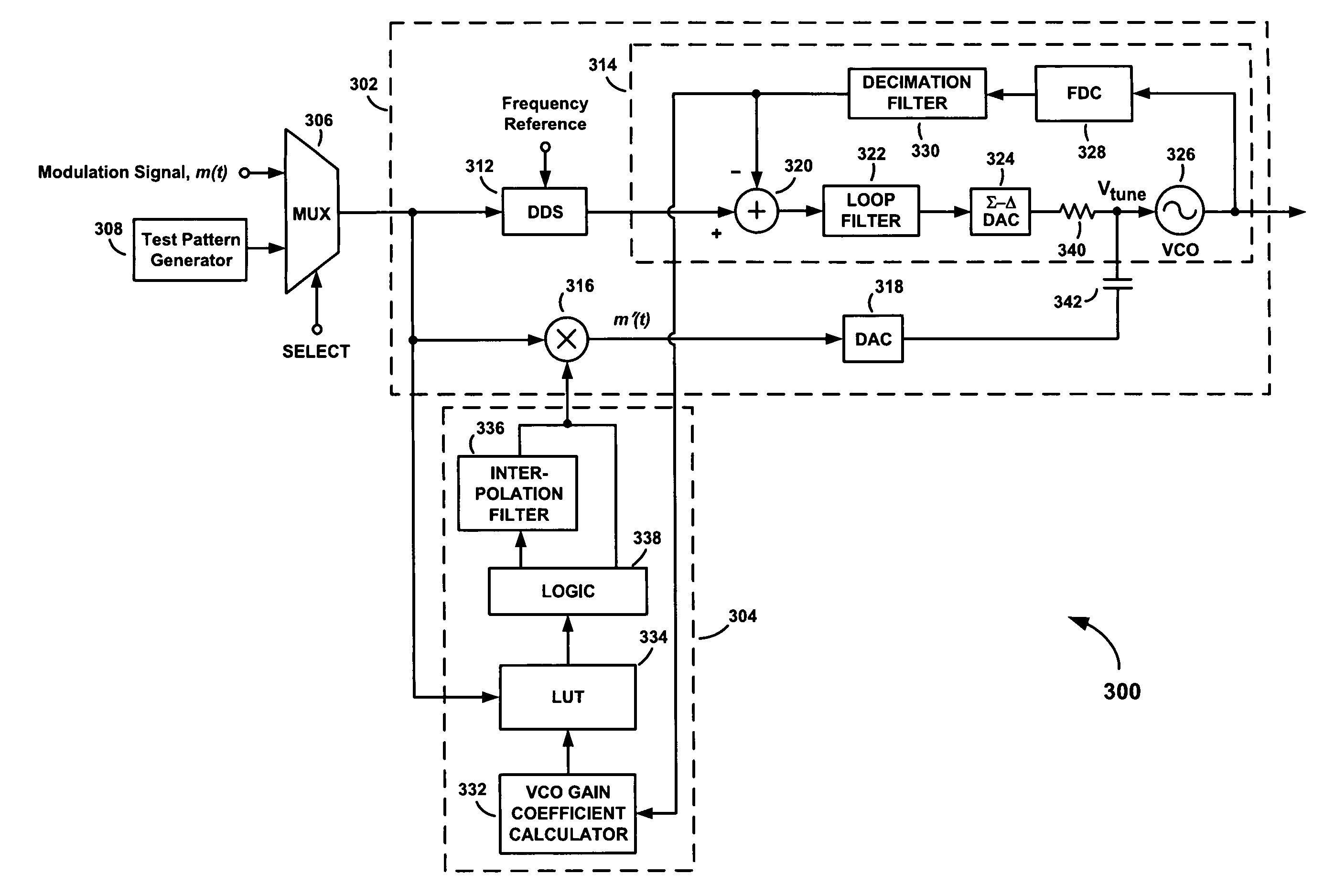
[0017]Referring to FIG. 3, there is shown a self-calibrating modulator apparatus 300, according to an embodiment of the present invention. The self-calibrating modulator apparatus 300 comprises a modulator 302, a voltage controlled oscillator (VCO) gain calibration circuit 304, and a multiplexer 306 for providing either a modulation signal m(t) or a test pattern signal from a test pattern generator 308 to the modulator 302. The modulator 302 includes a direct modulation path and a separate feed-forward path. A direct digital synthesizer (DDS) 312 and a frequency-locked loop (FLL) 314 are configured in the direct modulation path. A multiplier 316 and a digital to analog converter (DAC) 318 are configured in the feed-forward path. The FLL 314 comprises a summer 320, a digital loop filter 322, a sigma-delta (Σ-Δ) DAC 324, a VCO 326, a frequency-to-digital converter (FDC) 328, and a decimation filter 330.

[0018]The VCO gain calibration circuit 304 comprises a VCO gain coefficient calcula...


PUM


Abstract

A self-calibrating modulator apparatus includes a modulator having a controlled oscillator and an oscillator gain calibration circuit. The oscillator gain calibration circuit includes an oscillator gain coefficient calculator configured to calculate a plurality of frequency dependent oscillator gain coefficients from results of measurements taken at the output of the controlled oscillator in response to a test pattern signal representing a plurality of different reference frequencies. The plurality of frequency dependent gain coefficients determined from the calibration process are stored in a look up table (LUT), where they are made available after the calibration process ends to scale a modulation signal applied to the modulator. By scaling the modulation signal prior to it being applied to the control input of the controlled oscillator, the nonlinear response of the controlled oscillator is countered and the modulation accuracy of the modulator is thereby improved.

Description

FIELD OF THE INVENTION[0001]The present invention relates to methods and apparatus for countering voltage controlled oscillator (VCO) nonlinearities in communication systems.BACKGROUND OF THE INVENTION[0002]A voltage controlled oscillator (or “VCO”) is a type of electrical oscillator that generates an oscillatory signal having a frequency that is dependent on a control voltage. VCOs play an important role in communication systems and other electronic systems. They are used in both analog and digital applications, and are essential components of radio frequency communications systems.[0003]FIG. 1 illustrates how a VCO is configured in a polar modulation transmitter 100. The polar modulation transmitter 100 comprises an amplitude modulator 102 in an amplitude modulation (AM) path, a VCO 104 in a phase modulation (PM) path, and a power amplifier (PA) 106. The amplitude modulator 102 functions to modulate a direct current power supply signal Vsupply according to amplitude variations in ...

Claims


Application Information

Patent Timeline
Patent Type & Authority Patents(United States)
IPC IPC(8): H03C3/00
CPCH03C3/08H03C3/0941H03C5/00H03C3/0975H03C3/0991H03C3/095
Inventor LEE, WAYNE S.KATO, AKIRAMATSUURA, TORU
Owner PANASONIC CORP
Why Eureka
Try Eureka