Reflective liquid crystal display apparatus

a liquid crystal display and reflector technology, applied in the field of reflective liquid crystal display devices, can solve the problems of reduced image quality of image displayed, diffraction and interference of light cast into the liquid crystal display device, and inability to control light easily, so as to achieve the effect of facilitating a high-contrast liquid crystal display apparatus

Inactive Publication Date: 2006-03-23
CANON KK
View PDF3 Cites 16 Cited by
  • Summary
  • Abstract
  • Description
  • Claims
  • Application Information

AI Technical Summary

Benefits of technology

[0015] At least one exemplary embodiment is directed to a high-contrast liquid crystal display apparatus that can reduce not only 0th order light from specular reflection off o

Problems solved by technology

Generally, with a liquid crystal display device used in liquid crystal projectors, pixels are arrayed in matrix fashion, and light cast into the liquid crystal display device exhibits diffraction and interference due to the shape of the pixel openings.
Moreover, diffracted (interference) light is reflected (transmitted) at a different angle from that of the specular reflection (0th order transmission), so phase difference error occurs du

Method used


Image

  • Reflective liquid crystal display apparatus
  • Reflective liquid crystal display apparatus
  • Reflective liquid crystal display apparatus

Examples


first exemplary embodiment

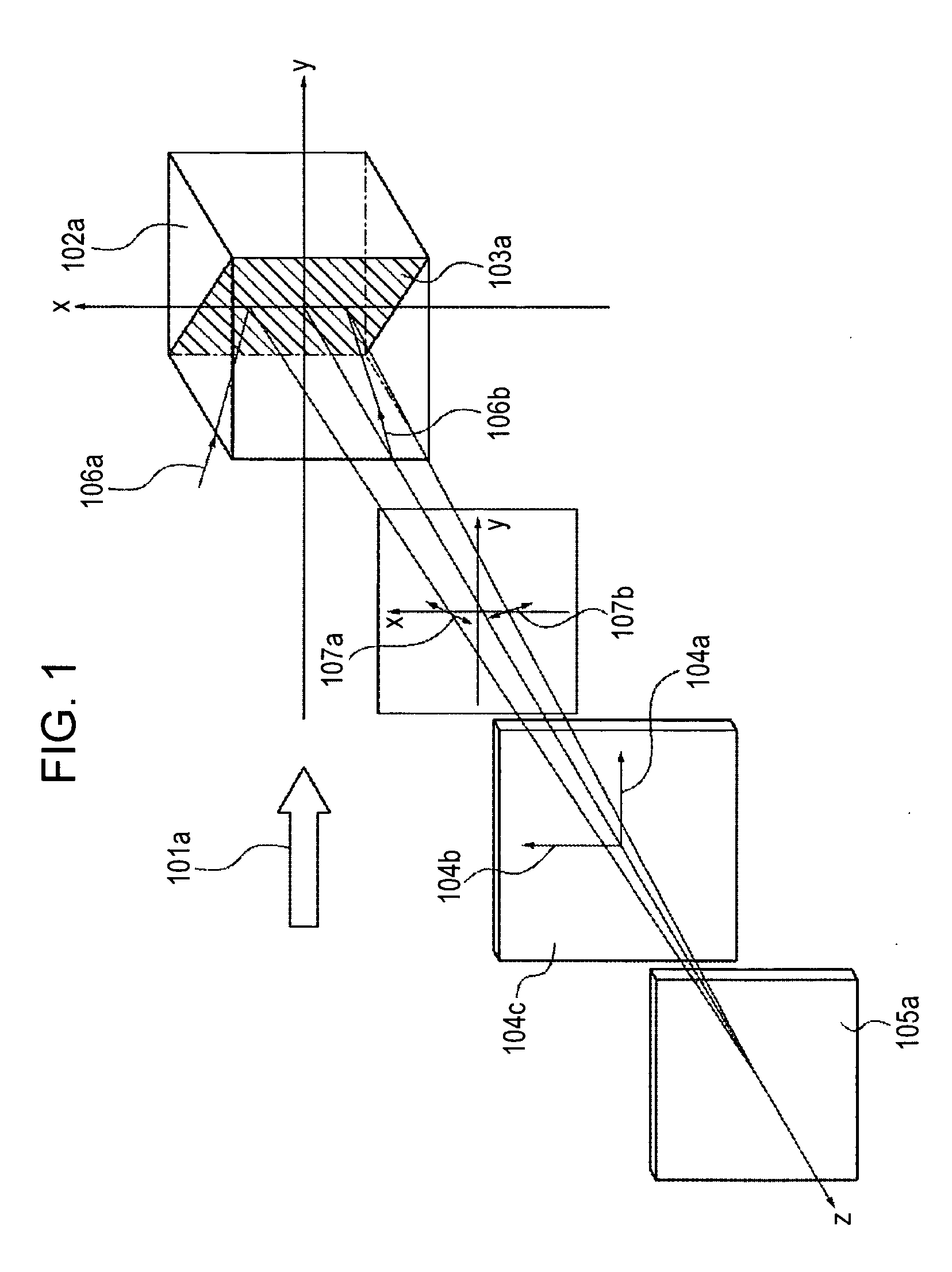
[0076]FIG. 1 illustrates a schematic diagram of a reflective liquid crystal display device according to at least one exemplary embodiment.

[0077] Reference numeral 101a denotes incident light, 102a denotes a polarization beam splitter, 103a a denotes a polarization split film of the polarization beam splitter 102a, 104c denotes a quarter wave plate, 104a denotes a slow axis and 104b denotes a fast axis, 105a denotes a reflective liquid crystal display device, 106a denotes incident light from the x positive direction within the xy plane, 106b denotes incident light from the x negative direction within the xy plane, 107a denotes the polarization axis according to which the incident light 106a can be inclined by the polarizing film 103a, 107b denotes the polarization axis according to which the incident light 106b can be inclined by the polarizing film 103a, the incident light axis in relation to the polarization beam splitter 102a is the y direction, the reflection light axis is the z...

second exemplary embodiment

[0160]FIG. 34 illustrates an overall diagram of a reflective liquid crystal display apparatus which is the second exemplary embodiment. In the drawing, components which are the same as those in FIG. 1 of the first exemplary embodiment have been provided with the same reference numerals.

[0161] In the drawing, reference numeral 301 denotes a one-dimensional integrator configured to form a substantially uniform intensity illumination distribution in a one-dimensional direction, configured of a cylindrical lens arrays 301a and 301b arrayed one-dimensionally, and 302a and 302b are light flux compression lenses for compressed illumination of the generally parallel light flux emitted from the light source 1, having curvature only with regard to the direction substantially orthogonal to the direction of array of the cylindrical lens arrays 301a and 301b.

[0162] Further, the light flux from the illumination optical system is subjected to color separation into the three colors or R, G, and B...


PUM


Abstract

At least one exemplary embodiment is directed to a reflective liquid crystal display apparatus which comprises: a polarization beam splitter having a polarization split film used as both a polarizer and an analyzer; a reflective liquid crystal display device; a quarter wave plate; and a projection optical system; where the absolute value of phase difference of diffracted light generated by the reflective liquid crystal display device in a black display state is reduced by the phase difference of the quarter wave plate, and thus the amount of stray light of the diffracted light guided from the polarizing beam splitter to the projection optical system decreases.

Description

BACKGROUND OF THE INVENTION [0001] 1. Field of the Invention [0002] The present invention relates to a reflective liquid crystal display apparatus. [0003] 2. Description of the Related Art [0004] A configuration is discussed in U.S. Pat. No. 5,327,270 to improve contrast of a reflective liquid crystal display apparatus. The configuration includes a polarization beam splitter used as both a polarizer and an analyzer, and a quarter wave plate, where the quarter wave plate is disposed in an optical path of light exiting the polarization beam splitter and being cast into the polarization beam splitter again, such that the fast axis or the slow axis thereof is substantially orthogonal to a plane containing the incident optical axis and reflected optical axis of the polarization beam splitter. [0005] The configuration of a conventional example of a reflective liquid crystal display apparatus is illustrated in FIG. 40. [0006] Reference numeral 22 denotes a polarization beam splitter, 25 de...

Claims


Application Information

Patent Timeline
IPC IPC(8): G02F1/1335
CPCG02B27/283G02F2001/13355G02F2001/133638H04N9/3197H04N5/7441H04N9/315G02F2203/02G02F1/13355G02F1/133638
Inventor ABE, MASAYUKI
Owner CANON KK
Why Eureka
Try Eureka