Power Management in Digital Receivers

a power management and digital receiver technology, applied in the field of digital receivers, can solve the problem that the device consumes and achieve the effect of consuming unnecessary power 90% of the tim

Active Publication Date: 2007-03-22
CSR TECH INC
View PDF16 Cites 77 Cited by
  • Summary
  • Abstract
  • Description
  • Claims
  • Application Information

AI Technical Summary

Benefits of technology

[0007] Typically, when designing a digital demodulation chip a designer targets some performance criteria corresponding to certain worst case operating conditions. These worst case operating conditions will be experienced only about 10% of the time that the device is operating. Because the worst case conditions require the greatest amount of processing power, the resulting device consumes unnecessary power 90% of the time. Methods and systems consistent with the present invention take advantage of the fact that the maximum processing power in a processing chip such as a digital demodulator chip, which corresponds to the worst case operating conditions, is only needed a small percentage of the time.

Problems solved by technology

Because the worst case conditions require the greatest amount of processing power, the resulting device consumes unnecessary power 90% of the time.

Method used


Image

  • Power Management in Digital Receivers
  • Power Management in Digital Receivers
  • Power Management in Digital Receivers

Examples


Embodiment Construction

[0018] Reference will now be made in detail to an implementation consistent with the present invention as illustrated in the accompanying drawings. Wherever possible, the same reference numbers will be used throughout the drawings and the following description to refer to the same or like parts. Although discussed with reference to these illustrations, the present invention is not limited to the implementations illustrated therein. Hence, the reader should regard these illustrations merely as examples of embodiments of the present invention, the full scope of which is measured only in terms of the claims following this description.

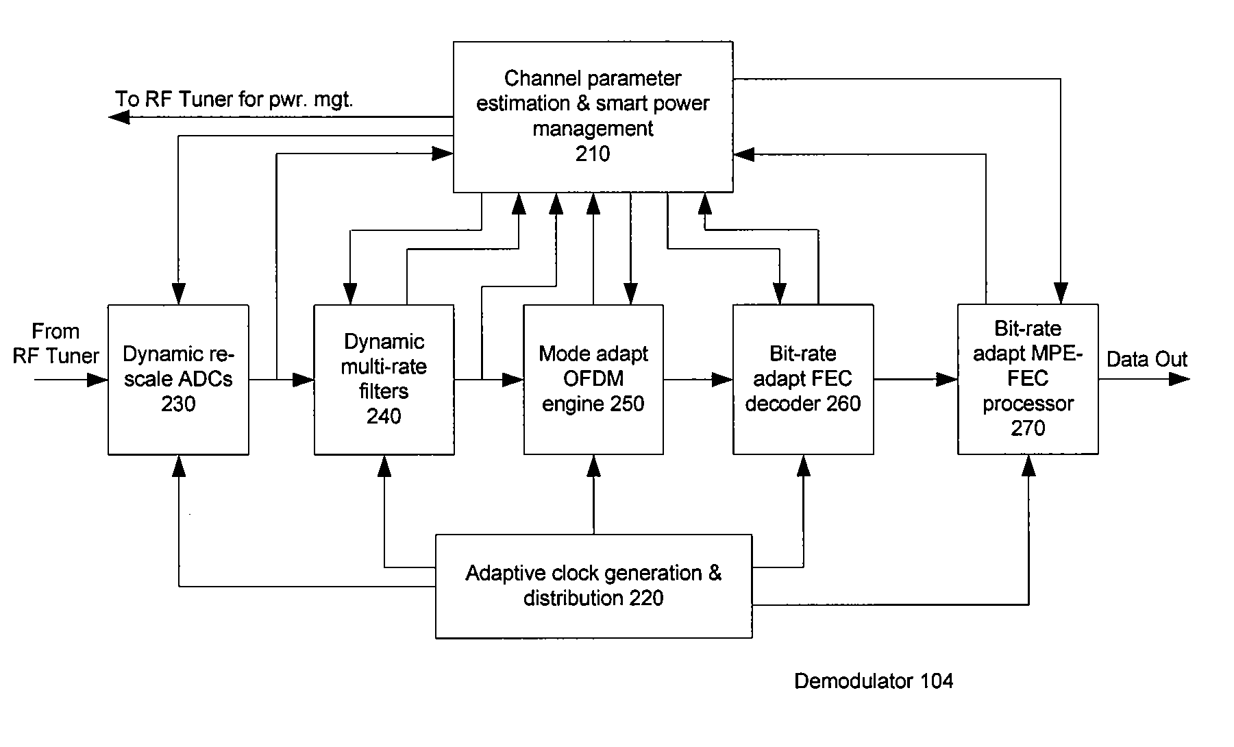
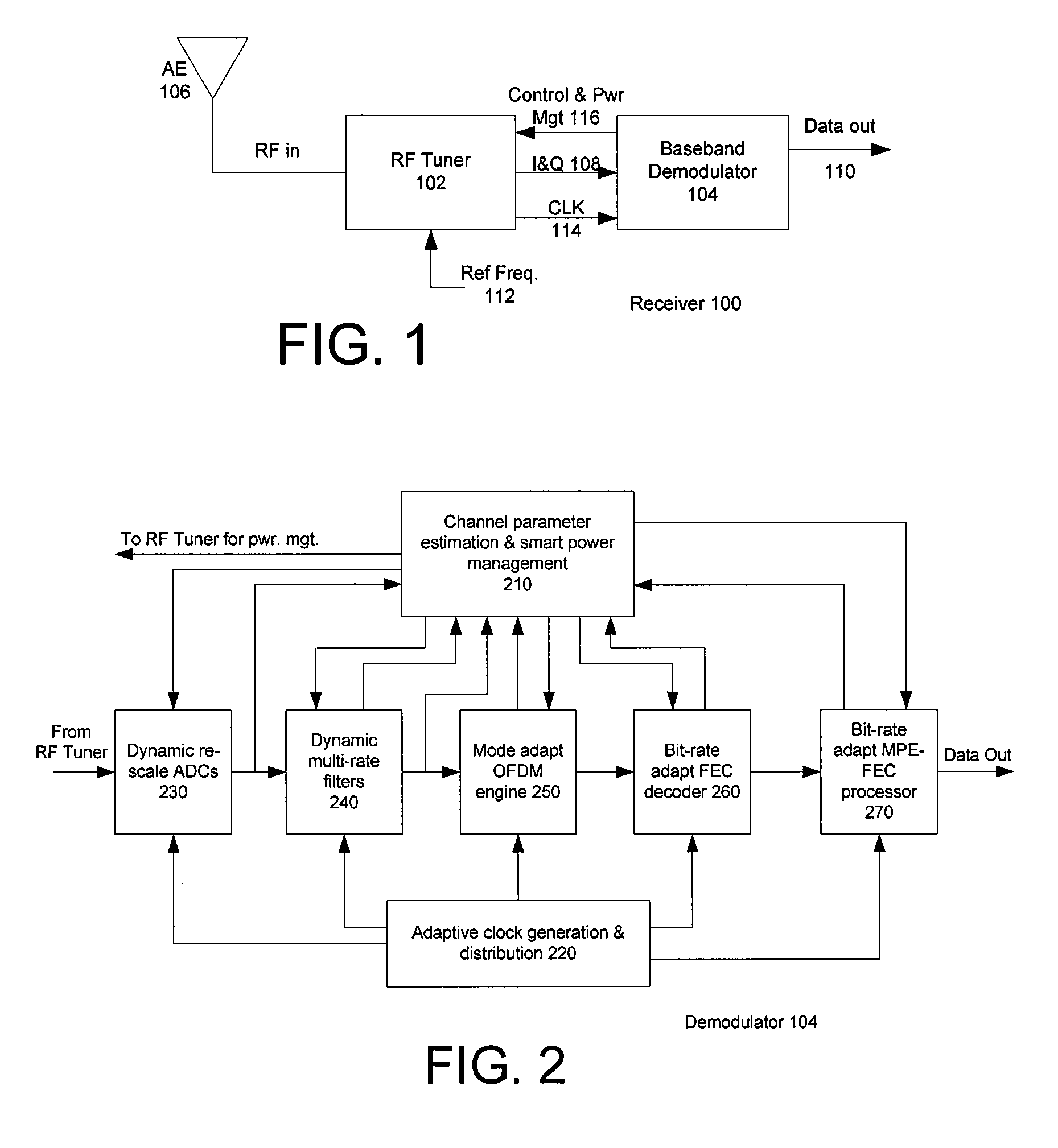
[0019] Referring first to FIG. 1, a simplified block diagram of a DVB-H receiver 100 is shown. Receiver 100 includes a radio frequency (RF) tuner section 102 and a baseband demodulator section 104. RF signals received by antenna 106 (which may be one or more antennas) are presented at the input of RF tuner 102. The tuner downconverts these RF signals and ...


PUM


Abstract

Methods and systems consistent with the present invention provide a method for dynamically controlling power consumption in a digital demodulator circuit by varying clock rates and bit widths of demodulator components including an analog to digital converter, decimation filter, OFDM operating engine, FEC decoder, and MPE-FEC processor, according to parameters and conditions of the received signal including modulation mode, signal to noise ratio, effective bit transmission rate, bit error rate, packet error rate, adjacent channel interference, and co-channel interference.

Description

CROSS-REFERENCE TO RELATED APPLICATIONS [0001] This application is a NONPROVISIONAL and claims the priority benefit of U.S. Provisional Application No. 60 / 677,439, entitled “Power Management in Digital Receivers,” filed on May 3, 2005, assigned to the assignee of the present invention and incorporated herein by reference.FIELD OF THE INVENTION [0002] The present invention relates to the field of digital receivers. More particularly, the invention relates to the field of power management in digital receivers. BACKGROUND [0003] The telecommunications industry, through the European Broadcasting Union, has promulgated a set of standards for digital video broadcasting (DVB). Among the most recent of such standards is one (entitled ETSI EN 302 304, “Digital Video Broadcasting Transmission System for Handheld Terminals”) related to digital video broadcasting (DVB) to a handheld device (DVB-H), which sets forth agreed upon requirements for delivering live broadcast television to mobile phon...

Claims


Application Information

Patent Timeline
Patent Type & Authority Applications(United States)
IPC IPC(8): H04L27/06H04K1/10
CPCH04L1/0045H04L1/0075H04L1/203H04N21/42607H04N21/4436H04L27/2601
Inventor LUU, HOWARD K.
Owner CSR TECH INC
Why Eureka
Try Eureka