Automatic gain control and low power start-of-packet detection for a wireless LAN receiver

a packet-based radio receiver and automatic gain control technology, applied in the field of wireless devices, can solve the problems of small bandwidth, inability to detect packets in time, and inability to know packet start time of wireless receivers, so as to achieve the effect of maximizing signal-to-noise-plus-distortion

Inactive Publication Date: 2007-03-22
CISCO TECH INC
View PDF17 Cites 61 Cited by
  • Summary
  • Abstract
  • Description
  • Claims
  • Application Information

AI Technical Summary

Benefits of technology

[0025] One embodiment uses AGC lookup tables to control amplifiers / attenuator blocks in a radio receiver. Given a signal strength measurement, these pre-computed lookup tables map the signal strength measurement into appropriate radio gain control bits to maximize signal-to-noise-plus-distortion at each stage in the radio receiver. Using such lookup tables provides flexibility; different tables may be used when there are temperature changes, process variations, and so forth.

Problems solved by technology

Prior art wireless systems have in general been limited to rather modest data rates.
Such small bandwidth can be aggravating in modern Internet uses.
Furthermore, a wireless receiver does not know when packets start.
Furthermore, the high data rates of newer wireless data networks lead to problems when trying to include AGC in receivers.

Method used


Image

  • Automatic gain control and low power start-of-packet detection for a wireless LAN receiver
  • Automatic gain control and low power start-of-packet detection for a wireless LAN receiver
  • Automatic gain control and low power start-of-packet detection for a wireless LAN receiver

Examples


embodiment 300

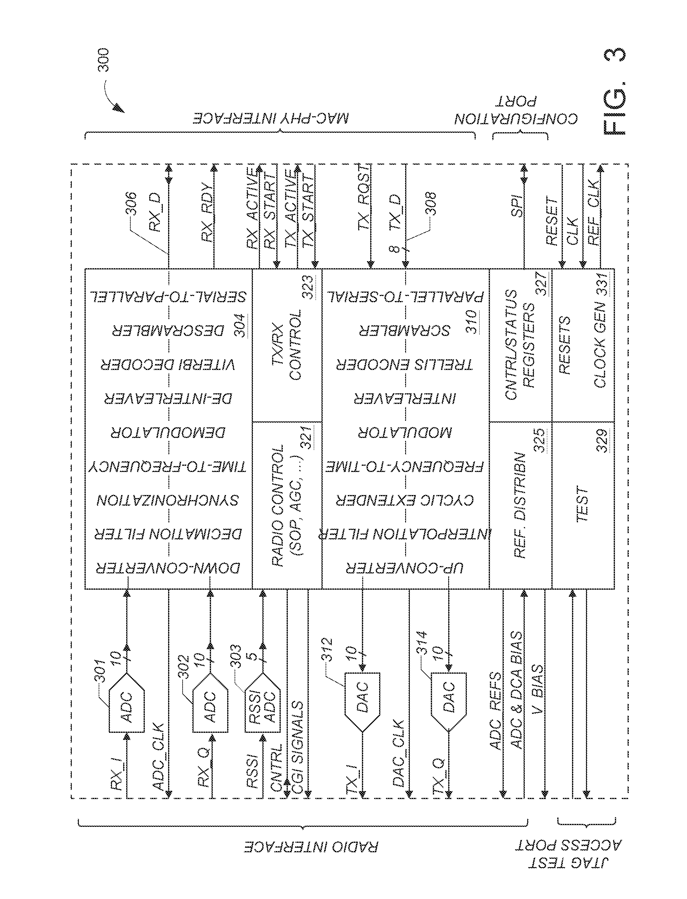
[0050]FIG. 3 shows in simplified block diagram form, an embodiment 300 of the modem chip that can operate with the transceiver chip. ADCs 301 and 302 accept fully differential I and Q analog signals from one embodiment of the transceiver chip, or one of the ADCs accepts a single differential signal from a single sideband embodiment of the transceiver chip. The receive signal processor 304 accepts the digitized receive signals from ADCs 301 and 302 and carries out the following operations: down-conversion, anti-alias filtering, OFDM carrier and symbol synchronization, time-to-frequency conversion, pilot tracking, sub-carrier demodulation, de-interleaving, Viterbi decoding, descrambling, and serial-to-parallel conversion. The output 306 of the receive processor 304 goes to an off-chip MAC processor.

[0051] The receive input of modem 300 can interface to two basic receiver configurations. [0052] 1. A quadrature radio receiver with baseband I and Q differential outputs which are sampled ...

embodiment 400

[0067] The transceiver embodiment 400 includes a bias supply 440 to supply bias to the various subcircuits, and digital system processor 442. In one embodiment, the bias supply 440 is programmable, and controlled by digital system processor 442. Processor 442 is a digital circuit that in one embodiment is on the same substrate as the receiver subsystem 413 and transmitter 417, and that includes one or more—say N— registers 437, a microcontroller called the RAD16 herein, and a system processor interface (transceiver SPI) 451. The transceiver SPI, also referred to as the transceiver configuration port, provides access to the registers 437, and in one embodiment, is a serial port. The digital system processor 442 provides a set of bias control signals to the bias supply. In one embodiment, the bias supply 440 includes a main bias generator that provides bias currents in units that are defined by an external reference resistor RREF. Selecting different values for RREF is one way of prov...


PUM


Abstract

A digital AGC system for burst operation, particularly suited for receiving packets in a wireless local area network. One embodiment includes a log detector that provides a signal strength measure, called the received signal strength indication (RSSI) over a wide dynamic range. The AGC system includes estimating the power in a received signal by averaging the log of the signal power. The Start of Packet detection avoids using the radio receiver's main analog to digital converters to preserve power.

Description

RELATED PATENT APPLICATIONS [0001] The present invention is a continuation of U.S. patent application Ser. No. 10 / 095,668 file Mar. 8, 2002 and titled “AUTOMATIC GAIN CONTROL AND LOW POWER START-OF-PACKET DETECTION FOR A WIRELESS LAN RECEIVER.” The contents of such U.S. patent application Ser. No. 10 / 095,668 are incorporated herein by reference. [0002] U.S. patent application Ser. No. 10 / 095,668 claims priority of the following U.S. provisional patent applications: [0003] Ser. No. 60 / 277,370 entitled SYSTEM USING SINGLE CHIP WIRELESS LAN MODEM AND SINGLE CHIP RADIO TRANSCEIVER AND APPARATI, METHODS, AND SOFTWARE PRODUCTS USED THEREIN OR THERE WITH, filed: Mar. 19, 2001, Attorney / Agent Ref. No.: CISRAD-100-P. [0004] Ser. No. 60 / 283,609 entitled WIRELESS COMMUNICATION SYSTEM, filed: Apr. 13, 2001, Attorney / Agent Ref No.: CISCO-4502-P. [0005] Ser. No. 60 / 322,382 entitled AUTOMATIC GAIN CONTROL AND LOW POWER START-OF-PACKET DETECTION FOR A WIRELESS LAN RECEIVER, filed Sep. 14, 2001, Att...

Claims


Application Information

Patent Timeline
Patent Type & Authority Applications(United States)
IPC IPC(8): H04B17/00H04B7/00
CPCH03G3/3078
Inventor RYAN, PHILIP J.ADAMS, ANDREW R.O'SULLIVAN, JOHN D.PARKER, URIHART, BRIANZYNER, GRZEGORZ B.
Owner CISCO TECH INC
Why Eureka
Try Eureka