Driveshaft assembly and method of manufacturing same

a technology of drive shaft and assembly, which is applied in the direction of couplings, instruments, static/dynamic balance measurement, etc., can solve the problems of undesirable adhesives and relatively difficult weld balance weights, and achieve the effects of facilitating the welding process, protecting from damage, and relative eas

Inactive Publication Date: 2007-03-22
DANA AUTOMOTIVE SYST GRP LLC
View PDF1 Cites 126 Cited by
  • Summary
  • Abstract
  • Description
  • Claims
  • Application Information

AI Technical Summary

Benefits of technology

[0006] This invention relates to an relates to an improved structure for an article, such as a driveshaft assembly for use in a drive train system, that is balanced for rotation during use, and to a method of manufacturing same. An annular sleeve is disposed about a portion of the article and is secured thereto, such as by welding, adhesives, frictional engagement, and the like. After the sleeve is secured to the article, one or more balance weights can be secured to the sleeve at desired locations to balance the article for rotation. The balance weights can be secured to the sleeve in any suitable manner, such as by welding, adhesives, and the like. The sleeve functions as a mounting surface upon which the balance weights can be secured to balance the article for rotation. Because the balance weights are secured not directly to the article, but rather are mounted indirectly thereon by the sleeve, the article is protected from damage that might otherwise result from welding the balance weights directly thereto.
[0007] Specifically, this invention relates to a structure for facilitating the welding of a balance weight to a lightweight rotatable tube, such as an aluminum driveshaft tube. A typical vehicular driveshaft assembly includes a hollow cylindrical driveshaft tube having a pair of tube yokes secured to the ends thereof. Traditionally, the vehicular driveshaft assembly has been balanced for rotation by securing one or more balance weights to the outer surfaces of the driveshaft tube or the tube yokes. When the driveshaft assembly is formed from an aluminum material, it has been found to be relatively difficult to weld the balance weight thereto. Adhesives have also been found to be undesirable. This invention contemplates that a hollow cylindrical sleeve be press fit about a portion of the driveshaft assembly, and that the balance weight be welded to the sleeve. Specifically, the sleeve (which is formed from a material that facilitates the welding process and does not react adversely to the adjacent aluminum material, such as steel) is press fit onto a portion of either or both of the tube yokes and the driveshaft tube so as to be fixed in position relative thereto. Then, one or more balance weights can be welded directly on the sleeve with relative ease. The sleeve is preferably press fit onto a relatively large diameter portion of the tube yoke adjacent to the universal joint so that (1) the balancing occurs relatively close to the rotational center of the universal joint and (2) relatively small balance weights can be used to achieve the desired balancing effect.

Problems solved by technology

When the driveshaft assembly is formed from an aluminum material, it has been found to be relatively difficult to weld the balance weight thereto.
Adhesives have also been found to be undesirable.

Method used


Image

  • Driveshaft assembly and method of manufacturing same
  • Driveshaft assembly and method of manufacturing same
  • Driveshaft assembly and method of manufacturing same

Examples


Embodiment Construction

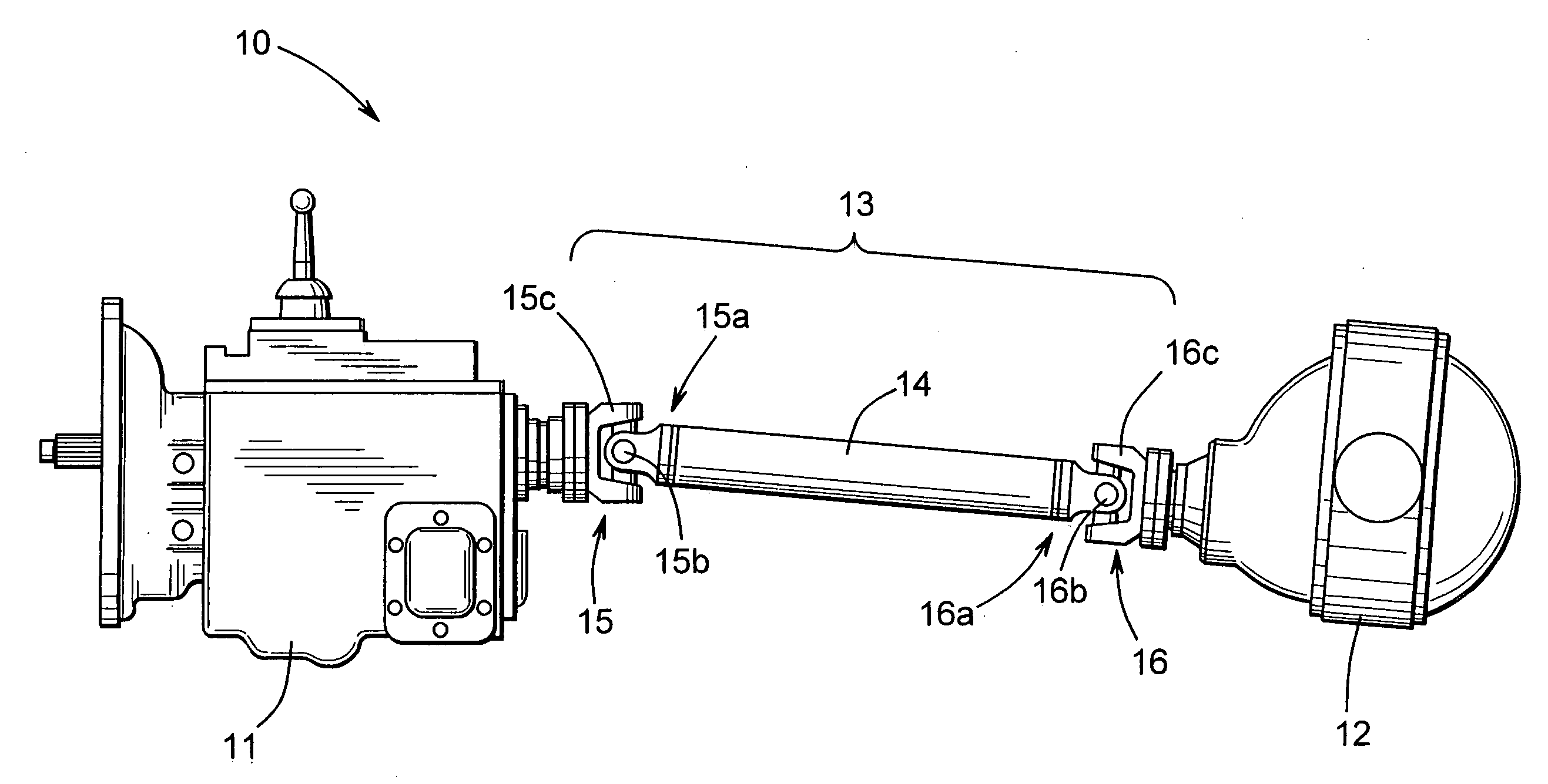
[0013] Referring now to the drawings, there is illustrated in FIG. 1 a drive train system, indicated generally at 10, in accordance with this invention. The illustrated drive train system 10 is, in large measure, conventional in the art and is intended merely to illustrate one environment in which this invention may be used. Thus, the scope of this invention is not intended to be limited for use with the specific structure for the drive train system 10 illustrated in FIG. 1 or with drive train systems in general. On the contrary, as will become apparent below, this invention may be used in any desired environment for the purposes described below.

[0014] The illustrated drive train system 10 includes a transmission 11 having an output shaft (not shown) that is connected to an input shaft (not shown) of an axle assembly 12 through a driveshaft assembly 13. The transmission 11 is rotatably driven by an engine (not shown) that generates rotational power in a conventional manner. The dri...


PUM

PropertyMeasurementUnit
weightaaaaaaaaaa
rotational poweraaaaaaaaaa
poweraaaaaaaaaa

Abstract

A driveshaft assembly includes a yoke including a body portion, a pair of opposed yoke arms that extends generally in a first axial direction from the body portion, and a neck portion that extends generally in a second axial direction from the body portion. A driveshaft tube is secured to the neck portion of the yoke, such as by magnetic pulse welding. A ring is secured to the body portion of the yoke, such as by press fitting, and a balance weight is secured to the ring, such as by welding.

Description

BACKGROUND OF THE INVENTION [0001] This invention relates in general to drive train systems for transferring rotational power from a source to a driven mechanism, such as from a vehicular engine / transmission assembly to an axle assembly. In particular, this invention relates to an improved structure for a driveshaft assembly for use in such a drive train system that is balanced for rotation during use, and to a method of manufacturing same. [0002] Drive train systems are widely used for generating power from a source and for transferring such power from the source to a driven mechanism. Frequently, the source generates rotational power, and such rotational power is transferred from the source to a rotatably driven mechanism. For example, in most land vehicles in use today, an engine / transmission assembly generates rotational power, and such rotational power is transferred from an output shaft of the engine / transmission assembly through a driveshaft assembly to an input shaft of an a...

Claims


Application Information

Patent Timeline
Patent Type & Authority Applications(United States)
IPC IPC(8): F16D3/16
CPCF16C3/02Y10S29/901Y10T464/40F16F15/322F16F15/34F16C2226/36F16D2300/22
Inventor KELLER, THOMAS J.DUGGAN, JAMES A.
Owner DANA AUTOMOTIVE SYST GRP LLC
Why Eureka
Try Eureka