
Conveyor for a windrower

a technology of conveying machine and windrower, which is applied in the field of conveying machine for windrower, can solve the problems of serious movement constraints, and achieve the effect of effective movemen

Active Publication Date: 2007-03-29
MACDON INDS
View PDF11 Cites 11 Cited by
  • Summary
  • Abstract
  • Description
  • Claims
  • Application Information

AI Technical Summary

Benefits of technology

[0010] It is one object of the invention to provide an improved swather which includes a swath conveyer which is effectively moveable between a raised storage position and an operating position.

Problems solved by technology

However this movement is seriously constrained by the construction of tractor in that the conveyor in both positions must be clear of the wheels and must move to a properly retracted position and to a properly located operating position.

Method used


Image

  • Conveyor for a windrower
  • Conveyor for a windrower
  • Conveyor for a windrower

Examples


Embodiment Construction

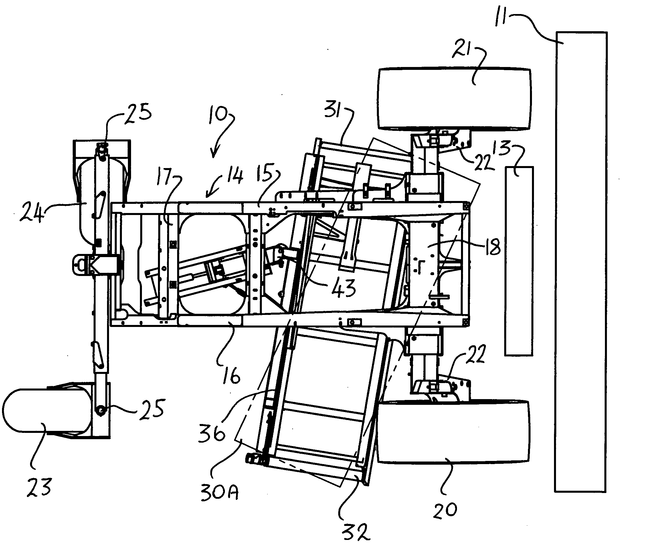
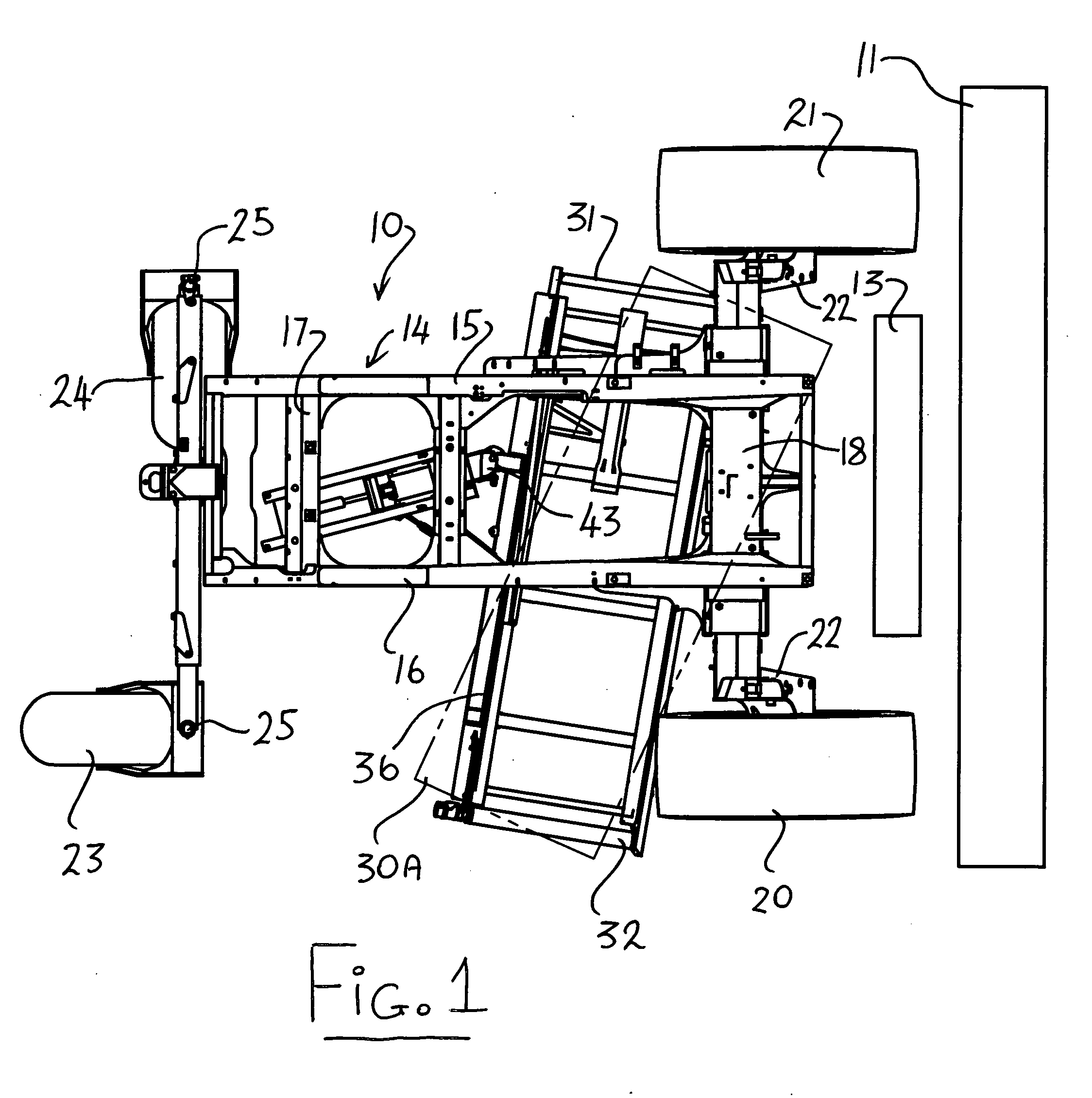
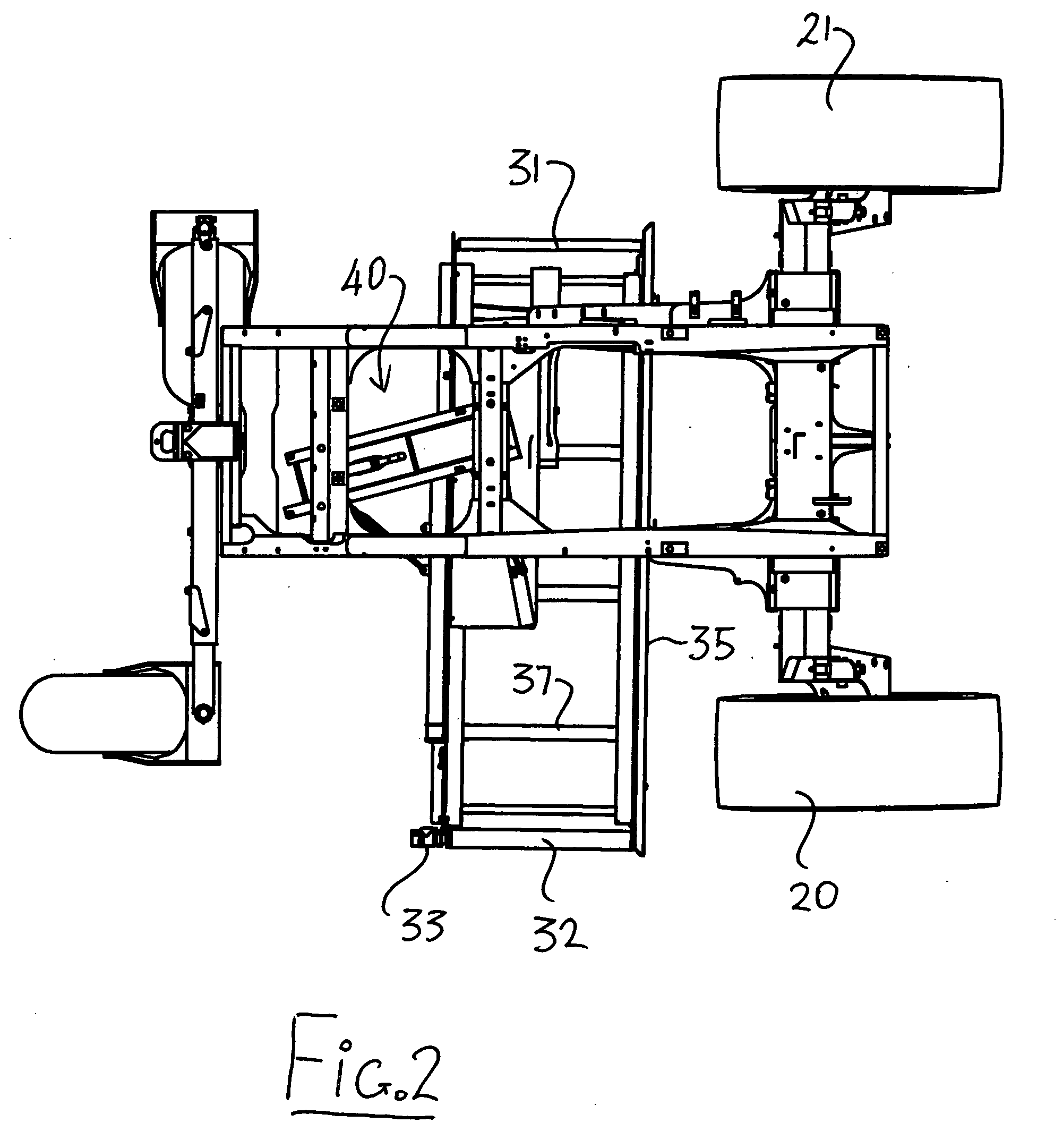
[0065] In the Figures is shown a swather or windrower which comprises a tractor 10, a header 11 and a crop conditioner 13. The header and crop conditioner are shown only schematically since these are well known to one skilled in the art and various different arrangements, locations and type can be provided. In most cases a conditioner is used in arrangements where a double windrow attachment is required but the conditioner is not essential provided the crop is transferred by some construction from the discharge to the belt described hereinafter.

[0066] The tractor 10 is also of a conventional nature and many different arrangements are well known to one skilled in the art. Basically a tractor of this type includes a frame 14 defined by a pair of longitudinally extending parallel rails 15 and 16 connected by suitable cross members 17 together with a front axle 18 and a rear axle 19. The front axle carries a pair of driven wheels 20 and 21 which are generally driven by hydraulic motors...


PUM


Abstract

A self-propelled swather has a frame mounted on ground wheels with a header in front which discharges between the wheels. A swath conveyor belt is located underneath the frame and arranged to convey the cut crop across the frame to a first discharge side of the frame. A mounting assembly including a beam across the belt and a lift arm mounts the swath conveyor for movement between a raised storage position in which the belt is horizontal underneath the frame and a lowered operating position in which the belt is inclined forwardly and downwardly while at the same time causing the beam to twist to cause the inlet end of the belt to move forwardly further than the discharge end to a forwardly inclined position between the front wheels.

Description

[0001] This invention relates to a swather otherwise known as a windrower and particularly to a conveyor arrangement which conveys the crop swath or windrow to one side of the frame for double windrowing. The term swather as used herein is synonymous with windrower and can include many different types of cutting systems such as sickle knife and disk cutters, many different types of crop converging systems including draper and auger and many different types of conditioning systems including nip rollers and flail rollers. BACKGROUND OF THE INVENTION [0002] It is well-known that self-propelled swathers include a tractor in the form of a tractor frame carried on a pair of widely spaced front driven ground wheels together with widely spaced rear castor wheels. At the front of the frame is mounted a header extending across the frame for cutting the standing crop with the header generally having components which convey the crop material inwardly to a discharge opening between the front whe...

Claims


Application Information

Patent Timeline
IPC IPC(8): A01D43/00
CPCA01D57/20A01D43/077
Inventor TALBOT, FRANCOIS R.CORMIER, DANIEL G.
Owner MACDON INDS
Learn More