
Test apparatus and method of measuring surface friction of a brake pad insulator material and method of use of a brake dynamometer

a technology of brake pad insulator material and test apparatus, which is applied in the direction of measuring devices, instruments, scientific instruments, etc., to achieve the effect of convenient testing and measuremen

Active Publication Date: 2007-03-29
WOLVERINE ADVANCED MATERIALS
View PDF10 Cites 40 Cited by
  • Summary
  • Abstract
  • Description
  • Claims
  • Application Information

AI Technical Summary

Benefits of technology

[0008] A test apparatus for measuring surface friction of the damping material is provided that allows relatively easy testing and measurement of friction in known (i.e., controlled) conditions. Measuring of the coefficient of friction under typical or other specifically controlled loading and temperature conditions is possible. The test apparatus allows determination of the frictional damping mechanism of a brake pad insulator, which has not heretofore been accomplished, possibly due to the unsuitability of known tests, as discussed above.
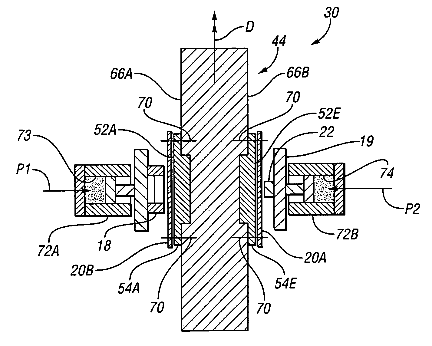
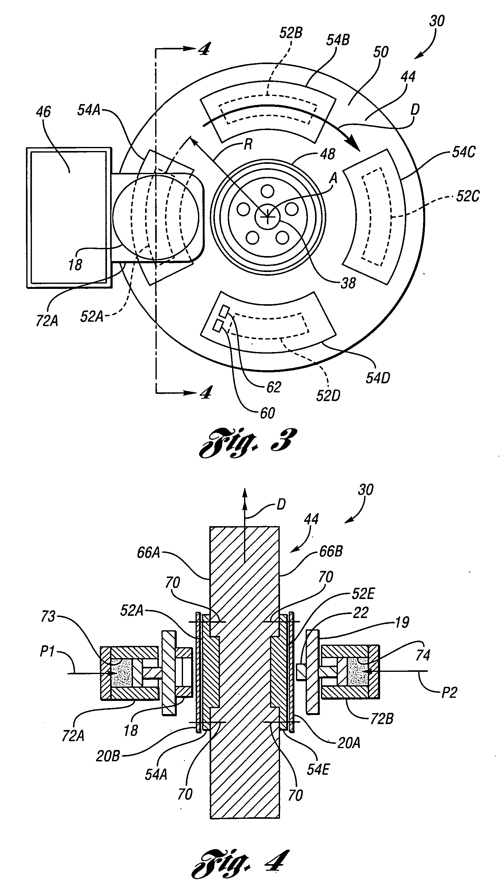
[0011] The test apparatus allows for easy and efficient testing of multiple samples of damping material at the same time and, if desired, different types of damping materials. Because the rotor is configured like a typical brake rotor having first outer surface and a second outer surface opposing the first outer surface, the first and a second sample of, preferably, the same insulator damping material may be outwardly supported at the respective outer surfaces. A brake piston and a caliper finger coupon (or, alternatively, two brake pistons; or, two caliper finger coupons) connected thereto act as first and second actuators employed to apply opposing axially-inward forces to the samples via the opposing piston and finger. A caliper finger “coupon” is a sample or section of a caliper finger that is used in a brake assembly employing the damping method. The first actuator applies an axially-inward force on the first sample and the second actuator applies an axially inward force on the second sample. More than one sample may also be tested on either the first or second outer surfaces of the rotor (i.e., on the same side of the rotor). The opposing axially-inward forces applied to the respective damping material samples are both toward the rotor and cancel one another so that the rotor is not loaded along its axis, reducing the need for a highly rigid support structure.
[0012] Preferably, carrier members are supported within recesses formed or machined in the rotor. The carrier members are supported for common rotation with the rotor and are operable for supporting the samples of the damping material. The recesses are spaced from one another either on the same side of the rotor or on different sides of the rotor (i.e., on the same or on both of the first outer surface and the second outer surface). The recesses permit multiple samples or types of materials to be tested under the same loading and temperature conditions.
[0017] The method may include creating a recess in the rotor and securing a carrier member at least partially within the recess for rotation with the rotor. The brake pad insulator material is then connected to the carrier member. Multiple recesses may be created so that multiple samples of brake pad insulator material, either of the same type of material or different types, may be tested at multiple carrier members supported within the recesses on the rotor. Repeated use of the carrier members from test to test is made simple by removing the brake pad insulator material from each carrier member and connecting (e.g., bonding) the second sample of brake pad insulator material to the carrier member and then repeating the steps of applying an axial force, measuring the axial force, powering the rotor and measuring torque to the rotor. Thus, calculation of surface friction of the second sample of brake pad insulator material is possible.
[0018] The test apparatus is well suited for use on a brake dynamometer. Specifically, the test apparatus has a configuration similar to a brake system (such as having a rotor, a stator and an actuator), which allows the use of a brake dynamometer so the appropriate loading may be applied and acquisition of relevant quantities can be carried out easily to evaluate friction between actual surfaces used in the brake system (i.e., using the actual brake pistons and fingers that will contact the brake pad insulator material). The existing controller (governing actuation, data acquisition and test automation) of the brake dynamometer is employed. Accordingly, a method of using a brake dynamometer includes providing a rotor, a stator, at least one actuator and damping material. The method includes operatively connecting the rotor with a rotatable shaft of the brake dynamometer for common rotation therewith. The method further includes grounding the stator and operatively connecting the actuator to the stator and to a controller on the brake dynamometer. Next, the damping material is operatively connected to the rotor and force is applied to the damping material via the actuator. The method includes rotating the rotor while the force is being applied and measuring torque on the rotor, thereby allowing calculation of surface friction of the damping material.

Problems solved by technology

The test apparatus allows determination of the frictional damping mechanism of a brake pad insulator, which has not heretofore been accomplished, possibly due to the unsuitability of known tests, as discussed above.

Method used


Image

  • Test apparatus and method of measuring surface friction of a brake pad insulator material and method of use of a brake dynamometer
  • Test apparatus and method of measuring surface friction of a brake pad insulator material and method of use of a brake dynamometer
  • Test apparatus and method of measuring surface friction of a brake pad insulator material and method of use of a brake dynamometer

Examples


Embodiment Construction

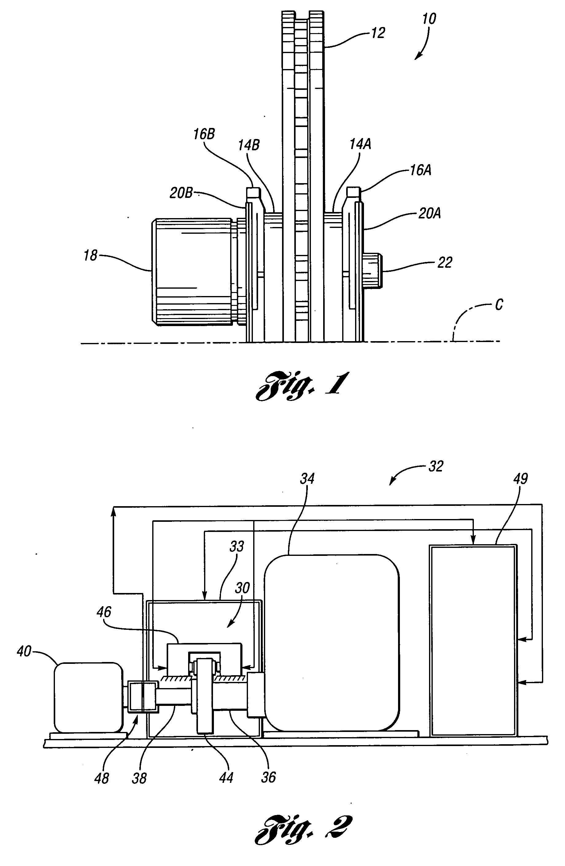
[0026] Referring to the drawings, wherein like reference numbers refer to like components, FIG. 1 shows a typical automotive disk brake assembly 10. The disc brake assembly 10 includes a disk rotor 12 rotating about a center line C. The rotor 12 will be operatively connected to a wheel that also rotates about center line C, as is well understood by those skilled in the art. An inner disk brake pad 14A and an outer disk brake pad 14B are axially moveable via brake piston 18 into contact with the disk rotor 12 for braking the rotor 12 and, thereby, the wheel. Each of the brake pads 14A, 14B is of a selected frictional material. Each brake pad 14A, 14B has a respective metal backing plate 16A, 16B adhered or otherwise connected to it outward of the brake disk rotor 12. Brake pad insulator material 20A, 20B, also referred to herein as damping material, is applied to the outer side of each respective of the backing plates 16A, 16B. The brake pad insulator material 20A, 20B may be multi-l...


PUM


Abstract

A test apparatus for measuring surface friction of a damping material such as brake pad insulator material includes a rotor configured to support the damping material for rotation therewith, an actuator pressurizable to apply axially-inward force to the damping material and a stator configured to support the actuator. A sensor determines the force applied to the actuator and a torque cell is axially aligned with the rotor for measuring torque of the rotor in relation to force applied to the damping material. The calculation of surface friction of the damping material is possible based on the measured load and torque. A method of measuring surface friction of a brake pad insulator material as well as a method using a brake dynamometer is also presented.

Description

TECHNICAL FIELD [0001] This application relates to an apparatus for testing damping material and specifically a method of measuring surface friction of automotive brake pad insulator material. BACKGROUND OF THE INVENTION [0002] Brake pad insulators are typically used on the backing plate of a disk brake. Brake pad insulators are designed to perform a damping function at various vibrations, frequencies and temperatures. The brake pad insulators thus help quiet vibrations and induced noise of the disk brake pad. [0003] Brake pad insulators exploit various damping mechanisms to achieve the desired noise reduction. It is hypothesized that insulators attenuate noise by extensional damping, shear-deformation, isolation damping and frictional damping. Extensional damping may also be referred to as free layer damping and involves relative movement of a relatively soft layer of material that is over, on or otherwise connected with a relatively stiff layer of material. If the stiff layer bend...

Claims


Application Information

Patent Timeline
IPC IPC(8): G01N19/02
CPCG01N19/02
Inventor MAHAJAN, SANJAY K.DENYS, ERIC
Owner WOLVERINE ADVANCED MATERIALS
Learn More