Intake-air control device for internal combustion engine

a control device and internal combustion engine technology, applied in the direction of machines/engines, mechanical equipment, instruments, etc., can solve problems such as detection output errors, and achieve the effects of reducing the number of components, reducing the displacement of sensor members, and reducing detection output errors

Inactive Publication Date: 2007-03-29
MITSUBISHI ELECTRIC CORP
View PDF4 Cites 16 Cited by
  • Summary
  • Abstract
  • Description
  • Claims
  • Application Information

AI Technical Summary

Benefits of technology

[0010] In the intake-air control device for an internal combustion engine according to the invention, the resin holder includes the supporting surface positioned on the plane intersecting substantially orthogonally to the axial line of the throttle shaft and the sensor member includes the resin mold coat having the first and second main surfaces opposing substantially in parallel with each other and the sensor member is held in the resin mold body with the first main

Problems solved by technology

However, since the sensor member is fixed in the interior of the cylindrical holder with the potting resin, and there is no guiding member that guides the sensor membe

Method used


Image

  • Intake-air control device for internal combustion engine
  • Intake-air control device for internal combustion engine
  • Intake-air control device for internal combustion engine

Examples


first embodiment

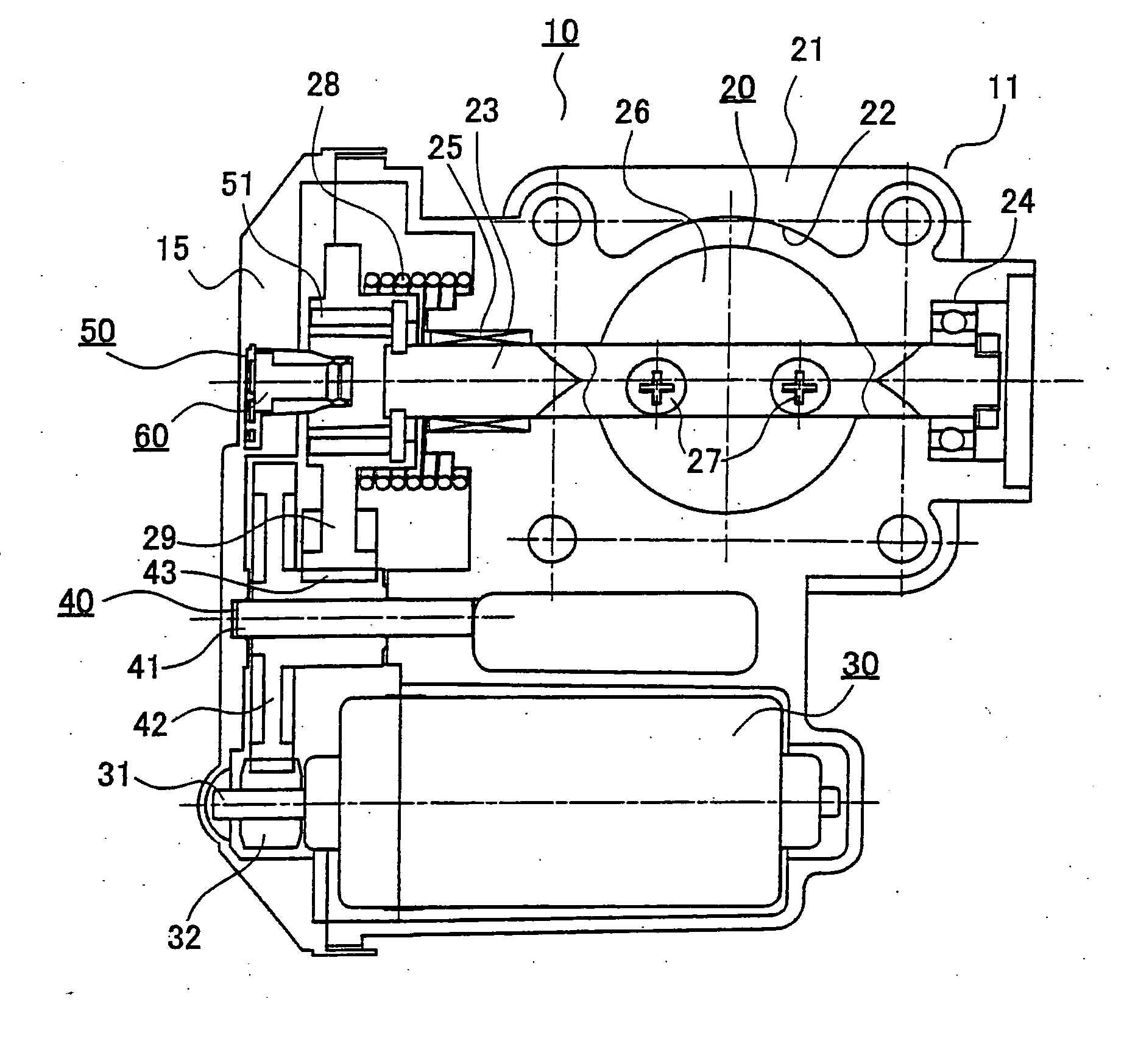
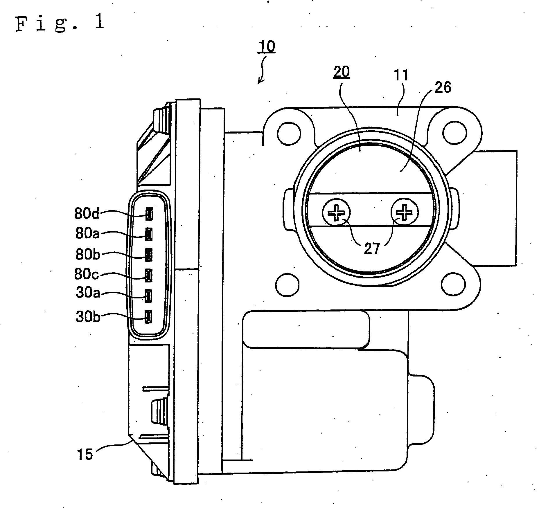
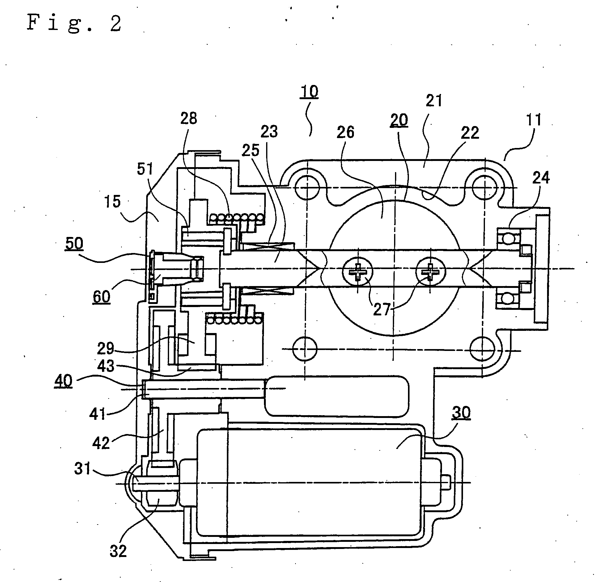
[0031]FIG. 1 is a front view showing a first embodiment of an intake-air control device for an internal combustion engine according to the invention; FIG. 2 is a vertical cross-sectional view showing a state in which part of FIG. 1 is left uncut; FIG. 3 is a side view of FIG. 1; FIG. 4 is a front view of a principal portion of a throttle position sensor in the first embodiment; FIG. 5 is a cross-sectional view of FIG. 4; FIG. 6 is an exploded perspective view in an assembling step of a magnetic field detecting assembly of the throttle position sensor according to the first embodiment; FIG. 7 is a perspective view of a stage in which assembly of the magnetic field detecting assembly of the throttle position sensor in the first embodiment is ended; FIG. 8 is a perspective view of a stage in which resin mold of the magnetic field detecting assembly of the throttle position sensor in the first embodiment is ended; FIG. 9 is a perspective view showing a state in which the magnetic field ...

second embodiment

[0084] Referring now to FIG. 14 to FIG. 19, a second embodiment of the intake-air control device for an internal combustion engine according to the invention will be described. FIG. 14 is a perspective view showing a state before assembly of a sensor circuit structure of a magnetic field detecting assembly and a resin holder according to the second embodiment; FIG. 15 is a perspective view showing a state before assembly of the sensor circuit structure and the resin holder to a terminal lead structure according to the second embodiment; FIG. 16 is a perspective view showing a state in which assembly of the magnetic field detecting assembly of a throttle position sensor is completed according to the second embodiment; FIG. 17 is a front view showing a state in which the magnetic field detecting assembly shown in FIG. 16 is completed; FIG. 18 is a cross-sectional view taken along the line E-E in FIG. 17; and FIG. 19 is a cross-sectional view taken along the line D-D in FIG. 17. All th...


PUM


Abstract

An intake-air control device for an internal combustion engine in which a sensor member can be positioned further accurately is provided. A throttle position sensor includes magnetic field generating means and a magnetic field detecting assembly. The magnetic field detecting assembly includes a plurality of terminal leads, a resin holder secured on the plurality of terminal leads, a sensor member generating a sensor output, and a resin mold body including the plurality of terminal leads, the holder, and the sensor member insert-molded. The resin holder includes a supporting surface which is located on a plane intersecting substantially perpendicularly to an axial line of a throttle shaft, and the sensor member includes a resin mold coat having first and second main surfaces opposing substantially in parallel to each other. The sensor member is held in the resin mold body with the first main surface of the resin mold coat in contact with the supporting surface.

Description

BACKGROUND OF THE INVENTION [0001] 1. Field of the Invention [0002] The present invention relates to an intake-air control device for an internal combustion engine. [0003] 2. Description of the Related Art [0004] The intake-air control device for an internal combustion engine includes a throttle valve and a throttle position sensor. The throttle position sensor serves to detect the rotational position of the throttle valve, and recently, a non-contact throttle position sensor is integrated. The non-contact throttle position sensor is effective for improving durability and enhancing detection accuracy. [0005] The non-contact throttle position sensor includes magnetic field generating means and a magnetic field detecting assembly. The magnetic field generating means rotates together with the throttle valve, and generates a detecting magnetic field in which the direction of magnetic field varies according to the rotation of the throttle valve. The magnetic field detecting assembly is f...

Claims


Application Information

Patent Timeline
IPC IPC(8): F02D11/10G01M19/00G01M99/00
CPCF02D9/105G01D5/145G01D5/00F02D2200/0404
Inventor KURITA, KAZUHISAONISHI, YOSHIHIKOURYU, TAKUYASAGAYAMA, TOMOKI
Owner MITSUBISHI ELECTRIC CORP
Why Eureka
Try Eureka