

Thermoelectric element
a technology of thermoelectric elements and electrodes, applied in the direction of thermoelectric devices with peltier/seeback effect, thermoelectric device details, electric devices, etc., can solve the problems of cracks, loose connection of the electrodes of the thermoelectric elements, and strain of all the thermoelectric elements constituting the thermoelectric device, etc., to achieve the effect of suppressing defects
- Summary
- Abstract
- Description
- Claims
- Application Information
AI Technical Summary
Benefits of technology
Problems solved by technology
Method used
Image

Examples
first embodiment
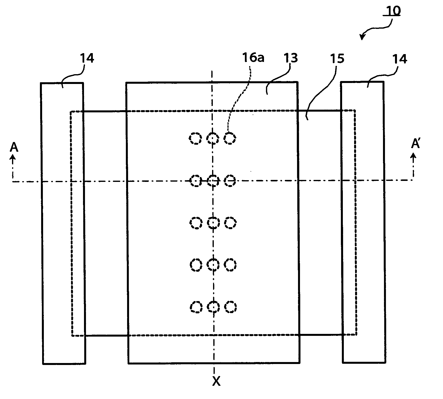
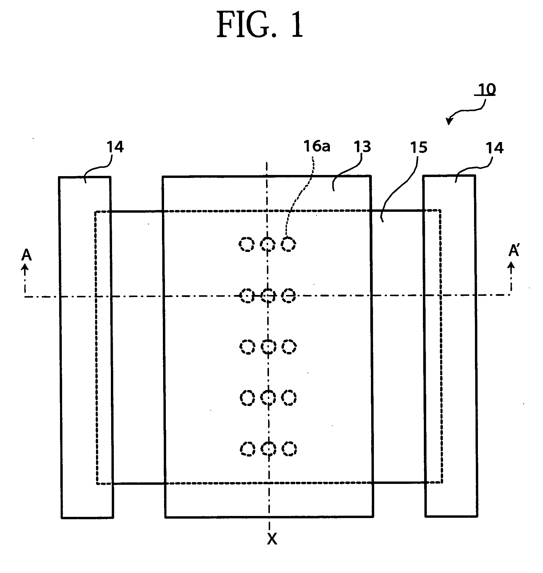
[0084] A thermoelectric element 10 according to the first embodiment of the present invention is shown in FIG. 1 and FIG. 2. For easier understanding, a first substrate 11 and a second substrate 12 shown in FIG. 2 are omitted in FIG. 1.
[0085] As shown in FIG. 1 and FIG. 2, the thermoelectric element 10 comprises a first substrate 11, a second substrate 12, a first electrode 13, a second electrode 14, a thermoelectric material 15, a stress releasing section 16, a silicon layer 20, and an insulating layer 21.
[0086] Since the first substrate 11 comes to have a high temperature upon receiving heat conducted from a high-temperature heat source (unillustrated), it is preferably made of a material having a small linear coefficient of expansion in order to suppress occurrence of a stress that might be produced in the first substrate 11, and made of, for example, invar alloy, or the like. The high-temperature heat source (unillustrated) is placed above the first substrate 11, and the first...
second embodiment
[0100] A thermoelectric element 30 according to the second embodiment of the present invention is shown in FIG. 3 and FIG. 4. The thermoelectric element 30 according to the present embodiment is different from the thermoelectric element 10 according to the first element in that a second stress releasing section 31 for releasing a stress is also provided between the second substrate 12 and the silicon layer 20. Those components that are the same as those in the first embodiment will be denoted by the same reference numerals and a detailed explanation for such components will be omitted.
[0101] As shown in FIG. 3 and FIG. 4, the thermoelectric element 30 comprises a first substrate 11, a second substrate 12, a first electrode 13, a second electrode 14, a thermoelectric material 15, a stress releasing section 16, a silicon layer 20, an insulating layer 21, and a second stress releasing section 31.
[0102] The second stress releasing section 31 is formed between the second substrate 12 a...
third embodiment
[0104] A thermoelectric element 50 according to the third embodiment of the present embodiment is shown in FIG. 5. The thermoelectric element 50 according to the present embodiment is different from the thermoelectric element 10 and the thermoelectric element 30 in that the silicon layer 20 has an opening 20c, and a part of a third stress releasing section 51 is formed between an electrode 56 and a second electrode 54. Those components that are the same as those in the first embodiment and second embodiment described above will be denoted by the same reference numerals, and a detailed explanation for such components will be omitted.
[0105] As shown in FIG. 5, the thermoelectric element 50 according to the present embodiment comprises a first substrate 11, a second substrate 12, a first electrode 13, a second electrode 54, a thermoelectric material 15, a stress releasing section 16, an electrode 56, a silicon layer 20, an insulating layer 21, and a third stress releasing section 51. ...
PUM
| Property | Measurement | Unit |
|---|---|---|
| thermoelectric | aaaaa | aaaaa |
| thermo-electromotive force | aaaaa | aaaaa |
| temperature | aaaaa | aaaaa |
Abstract
Description
Claims
Application Information