Testing apparatus and method for solar cells

a solar cell and test apparatus technology, applied in electrical apparatus, photovoltaic energy generation, photovoltaics, etc., can solve the problems of not being practicable to use the plurality of contact heads to contact isolated screen printed fingers, affecting the p-n junction under its surface, and not being able to test conventional front contact silicon crystalline solar cells. , to achieve the effect of efficient us

Inactive Publication Date: 2007-03-29
DAY4 ENERGY INC
View PDF19 Cites 80 Cited by
  • Summary
  • Abstract
  • Description
  • Claims
  • Application Information

AI Technical Summary

Benefits of technology

[0023] The method may further involve exposing the solar cell to light to cause the solar cell to produce and pass electric current to the fingers and gathering at the electrical conductor the electric current collected by the fingers to facilitate measurement of electric current collected by the fingers by the solar cell tester.
[0038] The holder may be operable to be connected to the solar cell tester, such that a contacting station of the solar cell tester can manipulate the holder to position the apparatus relative to the solar cell for use in testing the solar cell.
[0043] One advantage of the apparatus and methods described herein is the possibility to modify existing solar cell contacting stations for testing isolated finger solar cells, as well as solar cells having an integral current collecting bus connected to the fingers simply by exchanging a conventional front side contacting frame with the apparatus described above. The rear side contacting frame may be kept without replacement. More particularly, the apparatus described above can be efficiently used to test a large variety of PV cell types including crystalline silicon cells and EFG cells with or without front side bus bars as well as back side contact cells and any other type of solar cells with non-buried fingers.

Problems solved by technology

The above described solar cell testing equipment is currently widely used in industry for conventional screen printed PV cell testing however it cannot be used to test conventional front contact silicon crystalline solar cells that have isolated screen printed fingers without bus-bars.
It is not practical to use the plurality of contact heads to contact isolated screen printed fingers because the diameter of individual contacting tip heads is greater than the finger width and inevitably the sharp edges of the contact heads will contact the cell surface and penetrate the front of the cell, thereby damaging the p-n junction under its surface.
Smaller contacting tip heads are also problematic because it is practically impossible to maintain a precise shape, spacing and positioning of fingers during screen printing.
Clearly this equipment cannot be used in its current form to test the newer type of isolated finger solar cells, because existing test equipment requires the solar cell have built-in bus bars, whereas isolated finger-type solar cells do not have bus bars.

Method used


Image

  • Testing apparatus and method for solar cells
  • Testing apparatus and method for solar cells
  • Testing apparatus and method for solar cells

Examples


Embodiment Construction

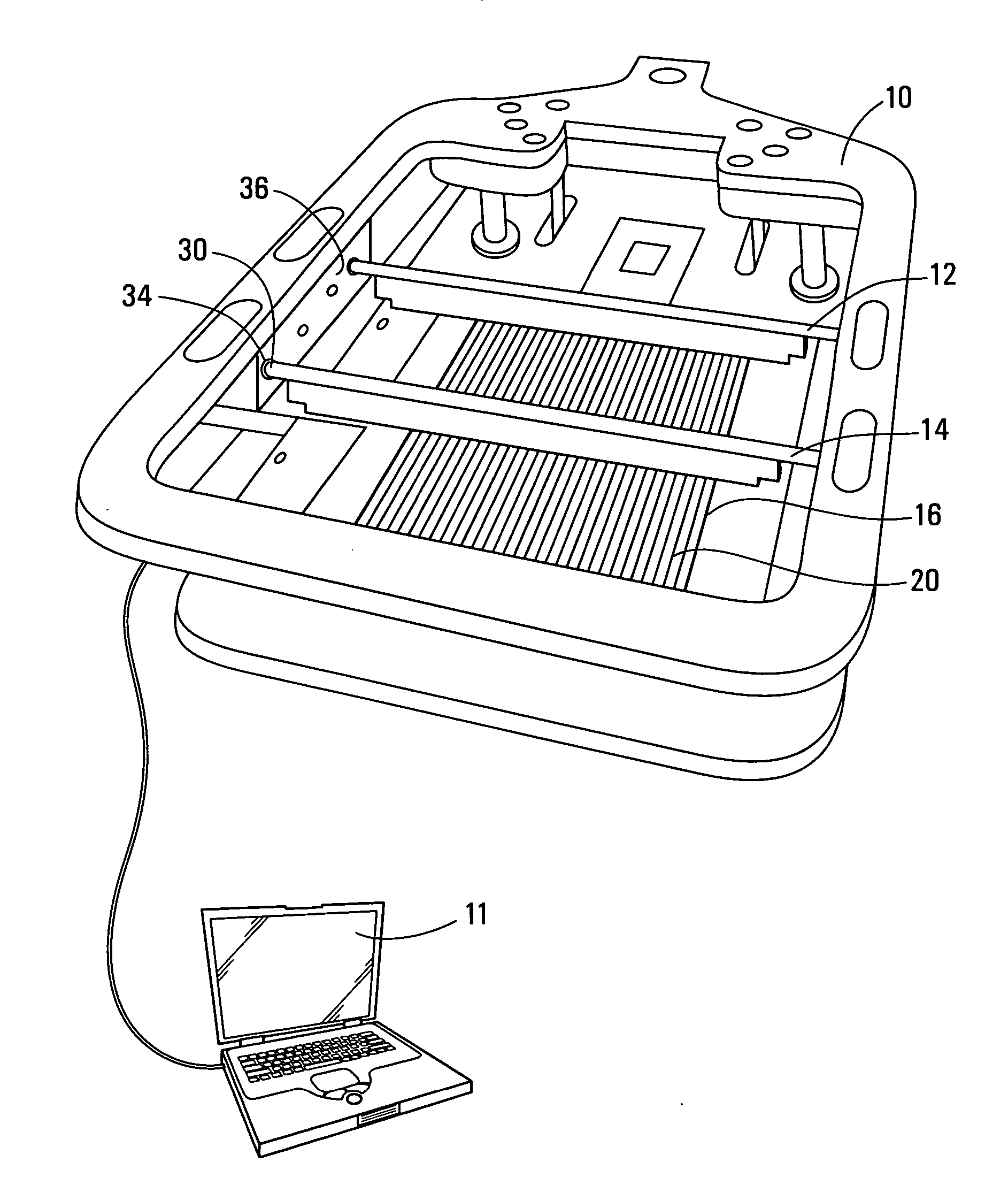
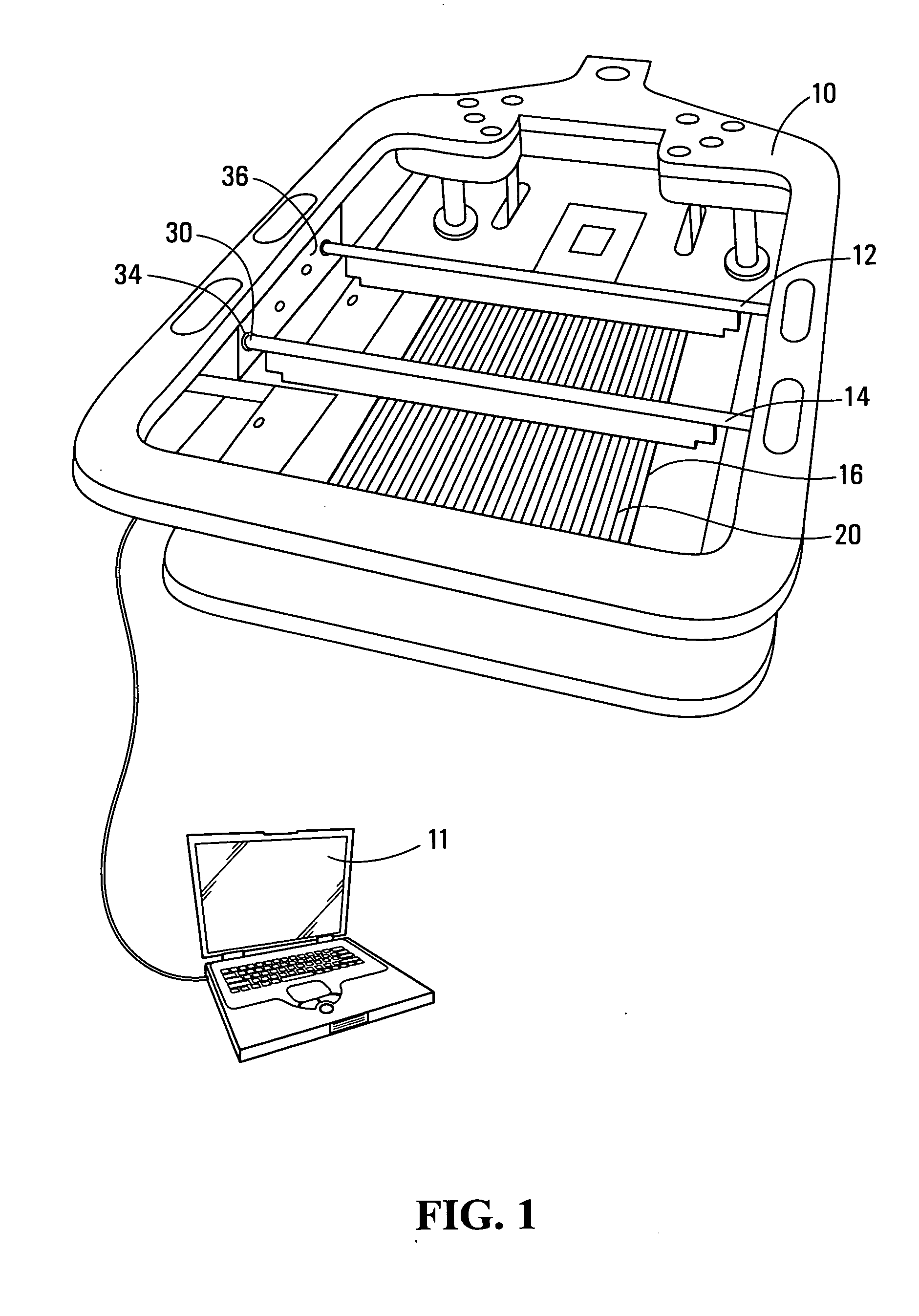
[0058] Referring to FIG. 1, a contacting station for solar cells is shown generally at 10. The contacting station 10 is, in this embodiment, a cetisPV-Contact1 contacting station for solar cells produced by H.A.L.M. Electronik GmbH, Sandweg 30-32, D-60316, Frankfurt am Main, of Germany and is connected to a solar cell test station 11. The contacting station 10 is conventional, with the exception of first and second apparatuses 12 and 14 that are specially designed for testing an isolated finger type solar cell 16 that does not employ integral bus bars for current gathering, but which are readily usable to alternatively test non-isolated finger type solar cells that do employ integral bus bars for current gathering.

[0059] The contacting station 10 is conventional and is normally intended for use in testing conventional solar cells that have a plurality of fingers that are electrically connected together by a bus bar permanently formed on the surface of the solar cell. The apparatuse...


PUM


Abstract

A method for temporarily electrically coupling to each of a plurality of current gathering fingers on a surface of a solar cell, to facilitate testing of the solar cell involves pressing a flexible elongate electrical conductor onto the surface of the solar cell such that an elongate contact surface of the electrical conductor extends across the surface of the solar cell to make electrical contact with substantially all of a surface of a bus connected to the fingers or at least a portion of each of the fingers, or both.

Description

BACKGROUND OF THE INVENTION [0001] 1. Field of Invention [0002] This invention relates to solar cell test equipment and methods and more particularly to methods and apparatuses for testing solar cells with or without bus bars. [0003] 2. Description of Related Art [0004] It is well-known that under light illumination photovoltaic (PV) solar cells generate electric current that is collected from the cell by front and rear electrical contacts. The front contact typically comprises a plurality of thin screen printed lines known as “fingers”, all connected to each other by two thicker screen-printed lines referred to as “bus bars” or “terminal bars”. The fingers collect electrical current from the PV cell itself and the bus bars receive the current from the fingers and transfer it away from the cell. [0005] Each screen printed finger has a width of approximately 120 microns, a height of between 5 and 20 microns and the spacing between the fingers is typically 1.5 to 3 mm. Technical limit...

Claims


Application Information

Patent Timeline
Patent Type & Authority Applications(United States)
IPC IPC(8): H02N6/00
CPCH02S50/10Y02E10/50
Inventor RUBIN, LEONID B.OSIPOV, ALEXANDER S.NEBUSOV, VALERY M.TARASENKO, VASILI Y.SCHNEIDER, ANDREAS
Owner DAY4 ENERGY INC
Why Eureka
Try Eureka