Flat plate heat transfer device

Inactive Publication Date: 2007-03-29
LS MTRON LTD
View PDF8 Cites 19 Cited by
  • Summary
  • Abstract
  • Description
  • Claims
  • Application Information

AI Technical Summary

Benefits of technology

[0010] The present invention is designed to solve the problems of the prior art, and therefore it is an object of the present invention to provide a flat plate heat transfer device with an improved inner structure, which is capable of becom

Problems solved by technology

In addition, together with the increased demands for high response of an electronic equipment and improvement of functions, energy consumption is also tending increased.
If there is no sufficient space for the working fluid to be dispersed from the evaporating part to the condensing part, the heat transfer mechanism using evaporation and condensation of the working fluid may be not appropriately realized, thereby deteriorating the performance of the heat transfer device.
However, since the conventional flat plate h

Method used


Image

  • Flat plate heat transfer device
  • Flat plate heat transfer device
  • Flat plate heat transfer device

Examples


experimental example

[0049] In order to evaluate the effects of the flat plate heat transfer device according to the present invention, inventors manufactured a flat plate heat transfer device with 40 mm, 70 mm and 0.65 mm in length, width and height. A flat case was composed by associating upper and lower cases separately as shown in FIG. 10, and they were made of a rolled copper foil with a thickness of 0.1 mm. A mesh included in the flat case was a copper screen mesh with a mesh number of 15, a diameter of the mesh wire of 0.20 mm, and a content of copper of 99% or above.

[0050] In order to make the flat plate heat transfer device to be used in this experiment, the screen mesh was positioned between the upper and lower cases so that each case is faced with the screen mesh as shown in FIG. 10, and then the upper and lower cases are sealed using denatured acrylic binary bond manufactured by DENKA in Japan (Trademark: HARDLOC) with a working fluid injection hole left.

[0051] And then, before a working f...


PUM


Abstract

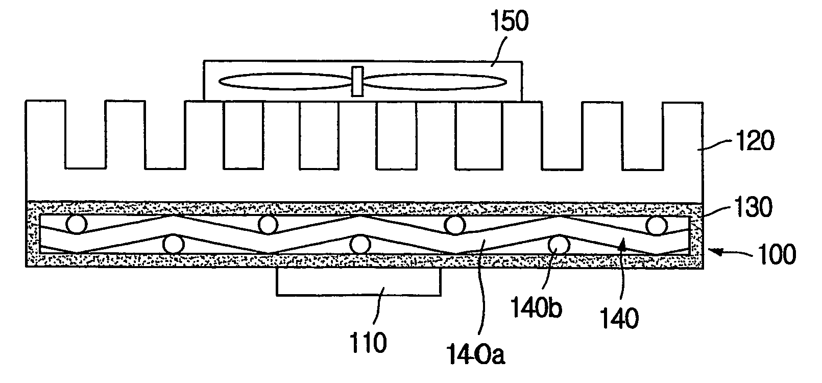
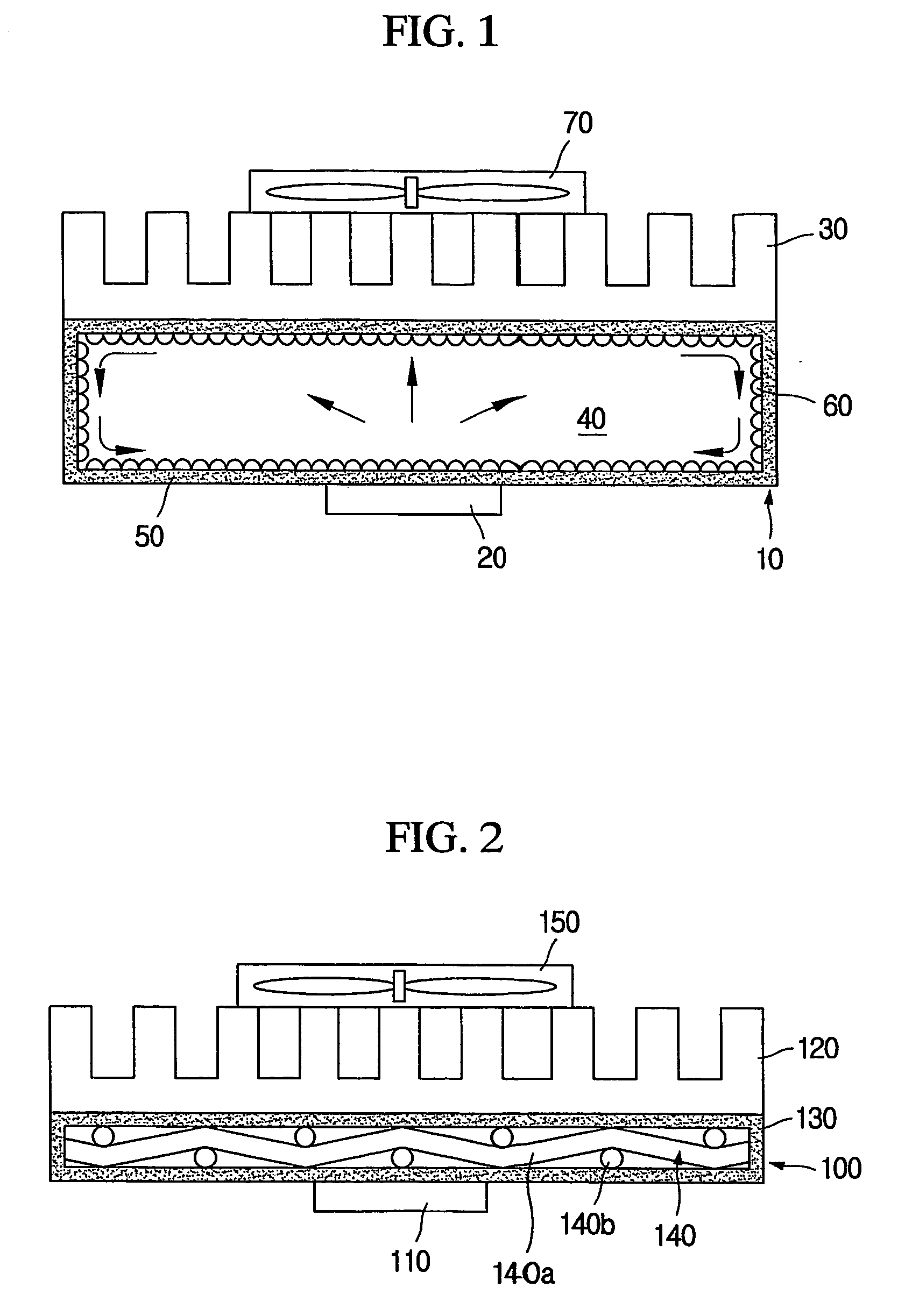
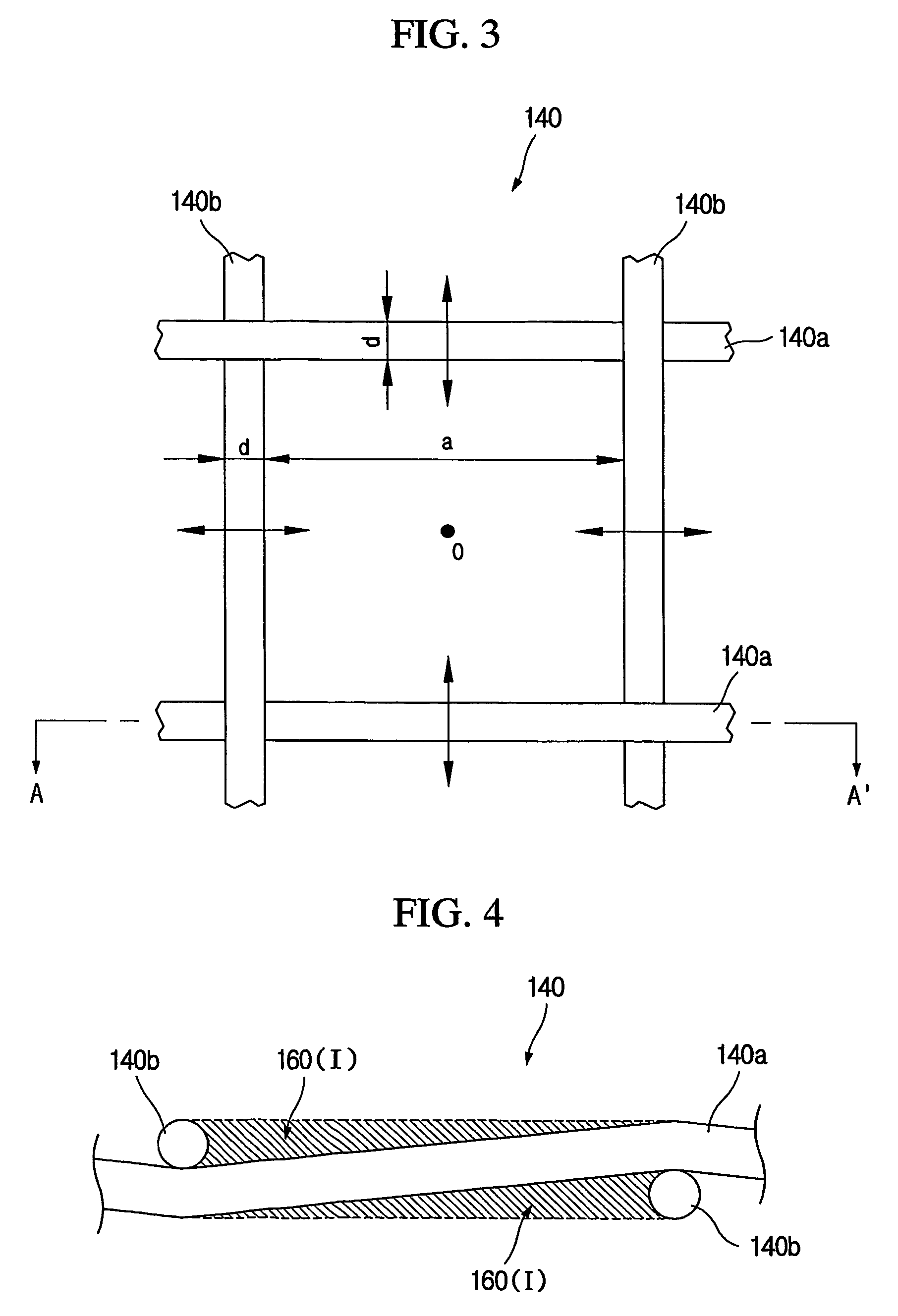
Disclosed is a flat plate heat transfer device, which includes a thermal-conductive flat case installed between a heat source and a heat emitting unit and containing a working fluid which is evaporated with absorbing heat from the heat source and is condensed with emitting heat to the heat emitting unit; and one layer of mesh installed in the flat case and configured so that wires are woven to be alternately crossed up and down. A dispersion channel of a vapor is formed along a surface of the wire from a cross point of the mesh near the heat source, and a flow channel of a liquid is formed by means of a capillary phenomenon along a length direction of the wire from a mesh lattice near the heat emitting unit to a mesh lattice near the heat source.

Description

TECHNICAL FIELD [0001] The present invention relates to a flat plate heat transfer device capable of transferring heat by means of a working fluid circulating mechanism using evaporation and condensation without applying a separate mechanical energy, and more particularly to an improved flat plate heat transfer device capable of having a thinner structure and preventing transformation caused by an external impact. BACKGROUND ART [0002] In recent, an electronic equipment such as notebook or PDA becomes smaller and thinner along with the development of integration technique. In addition, together with the increased demands for high response of an electronic equipment and improvement of functions, energy consumption is also tending increased. Accordingly, much heat is generated from electronic parts in the electronic equipment while the equipment is operated, so various flat plate heat transfer devices are used to emit the heat outside. [0003] A traditional example of the conventional ...

Claims


Application Information

Patent Timeline
IPC IPC(8): F28D15/00F28D15/02F28D15/04H01L23/373H01L23/427
CPCF28D15/0233H01L23/427H01L23/3733F28D15/046H01L2924/0002H01L2924/00F28D15/02
Inventor LEE, YONG-DUCKHONG, YOUNG-HOOH, MIN-JUNGKIM, HYUN-TAE
Owner LS MTRON LTD
Why Eureka
Try Eureka