Method and system for building up land in a water-covered or water-surrounded area and land body formed by use of same

a technology of building up land and water-covered areas, applied in water cleaning, land reclamation, soil-shifting machines/dredgers, etc., can solve the problems of increasing erosion, unbalanced erosion, and killing plants, and achieves precise control and less risk of fouling the device

Inactive Publication Date: 2007-03-29
SAMSUNG ELECTRONICS CO LTD +1
View PDF18 Cites 3 Cited by
  • Summary
  • Abstract
  • Description
  • Claims
  • Application Information

AI Technical Summary

Benefits of technology

[0015] Further in accordance with the purpose of the invention as embodied and broadly described herein, in another aspect, the inventor describes an embodiment of a system for building up land in a water-covered area. The system includes a plurality of floating boom segments, a wasteweir segment, and a sediment source. The boom segments and the wasteweir segment are connectable to form a shape that encloses an area wherein land is to be built up. The boom segments are connectable by connecting means as described further below. Each boom segment has a body that has a sieve panel attached thereto. Thus the assembled device includes an essentially closed shape formed by the boom segments and interrupted by the wasteweir segment. The assembled device also includes an essentially closed shape extending essentially between the water surface and the water bottom and interrupted by the wasteweir segment. The wasteweir segment enhances the rate of land formation by increasing the rate at which water from the sediment source may leave the enclosed area. Other embodiments of the invention may include multiple wasteweir segments or may omit wasteweir segments entirely. The wasteweir segment may be removed when the desired land body has been formed.
[0020] Optionally, each boom segment can also include a tiedown having a first end portion and a second end portion, the first end portion being attached to the body. The tiedown is secured so that its length under tension is approximately equal to the depth of the water and the length of the tiedown is at least approximately equal to the depth of the water. Preferably, the tiedown is fastened to the anchor line such that its length approximately equals the depth of the water. Tiedowns are intended to add strength to the boom segments and to keep the boom segments at the height of the wasteweir.
[0028] Further optionally, a sediment-containment structure may comprise one and preferably a plurality of stakes inserted into the water bottom outside the sediment-containment structure. These stakes may take the form of PVC or other pipes or any other body suitably stiff and strong for the application. Each stake is connected to a stake rope, which is connected to a stake-rope-to-mesh connector, which may take the form of a plastic clip attachable or attached to the mesh of a sieve panel or shared sieve panel. The stake-rope-to-mesh connector may include rings, apertures, cleats or other structures around which a cord or rope may be fastened. Where stakes and stake ropes are used, the height of a sieve panel may be selected to be substantially greater than the depth of the water, because the stake can hold the sieve panel under tension, there is less risk of fouling of the device. Also, the stakes may provide more precise control of the location and shape of the land mass formed using the structure. In this application, a land mass includes land built up above the water level in a water covered area and also includes a buildup of sediment on a water bottom decreasing the depth of water in that area. See FIG. 12 through 19. Note FIGS. 14 through 15 and 17 through 19; each set of figures shows a sequence in which sediment is added to an embodiment of the invention having stakes.

Problems solved by technology

Seasonal or unusual events such as floods or storms may cause erosion and sedimentation to become unbalanced for a time.
Killing the plants increases erosion because many plants hold the land together and help to absorb impacts of waves and other water flows.
When the plants die, erosion increases.
Fresh water diversion from rivers into coastal wetlands merely keeps salt water at bay and does little to promote land restoration, not only because of decreased sediment in leveed rivers but also because diversion of fresh water typically uses siphons or pipes that place sediment-containing water into a single location rather than over a broader plain.

Method used


Image

  • Method and system for building up land in a water-covered or water-surrounded area and land body formed by use of same
  • Method and system for building up land in a water-covered or water-surrounded area and land body formed by use of same
  • Method and system for building up land in a water-covered or water-surrounded area and land body formed by use of same

Examples


Embodiment Construction

[0045] The inventor now moves to a detailed description of an embodiment of the method of the invention, which is shown in the drawings, where like parts are labeled with like reference numerals. FIG. 6, is a flow chart depicting the steps that are involved in the embodiment depicted therein.

[0046] 1. Select a site where the method will be practiced. The site is typically a coastal marsh or wetland that has been eroded through a process that includes salt-water intrusion. Islands that have been degraded due to erosion can also be selected.

[0047] 2. Measure the dimensions of the site including the depth of the water contained at various locations around the site.

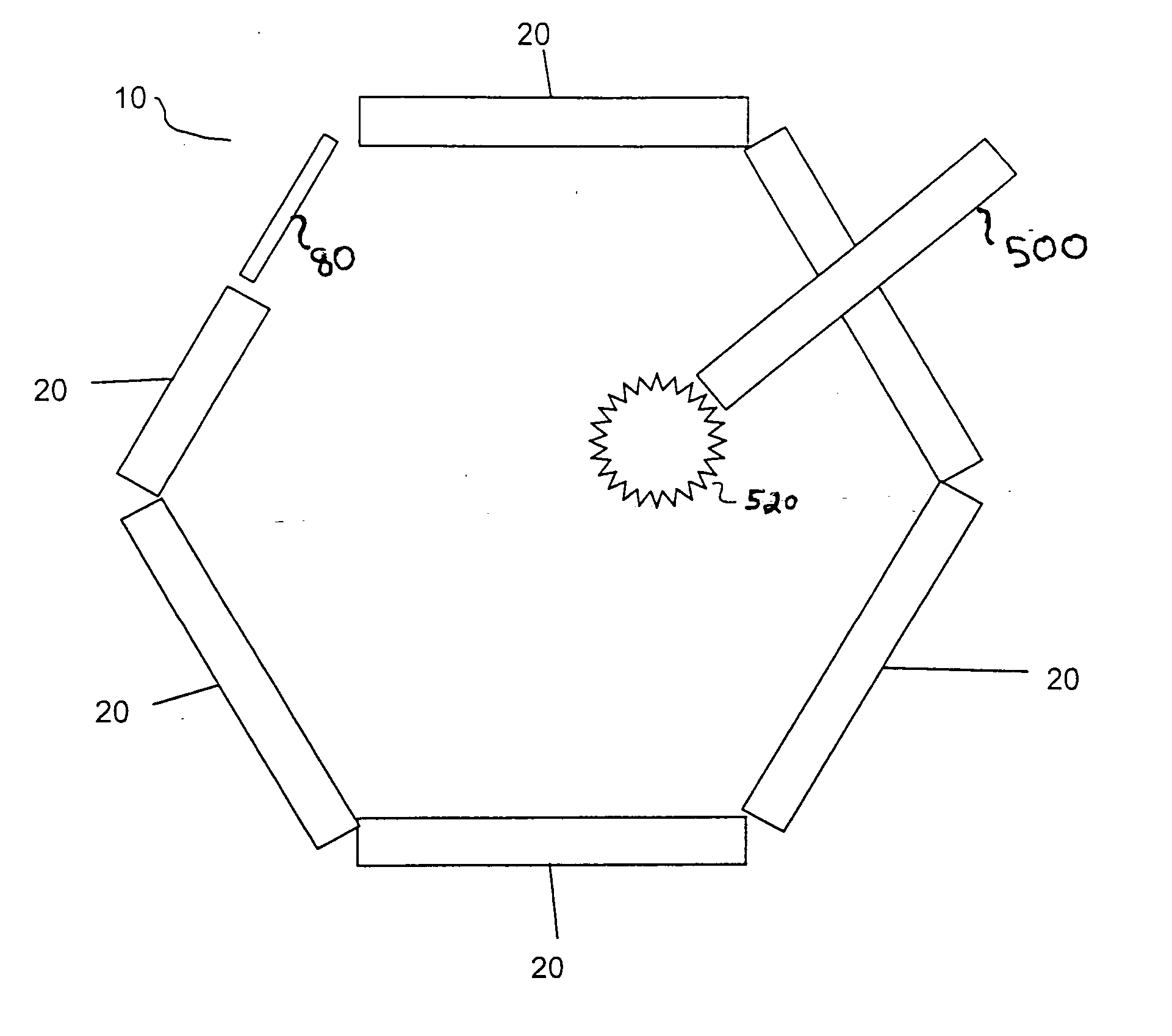
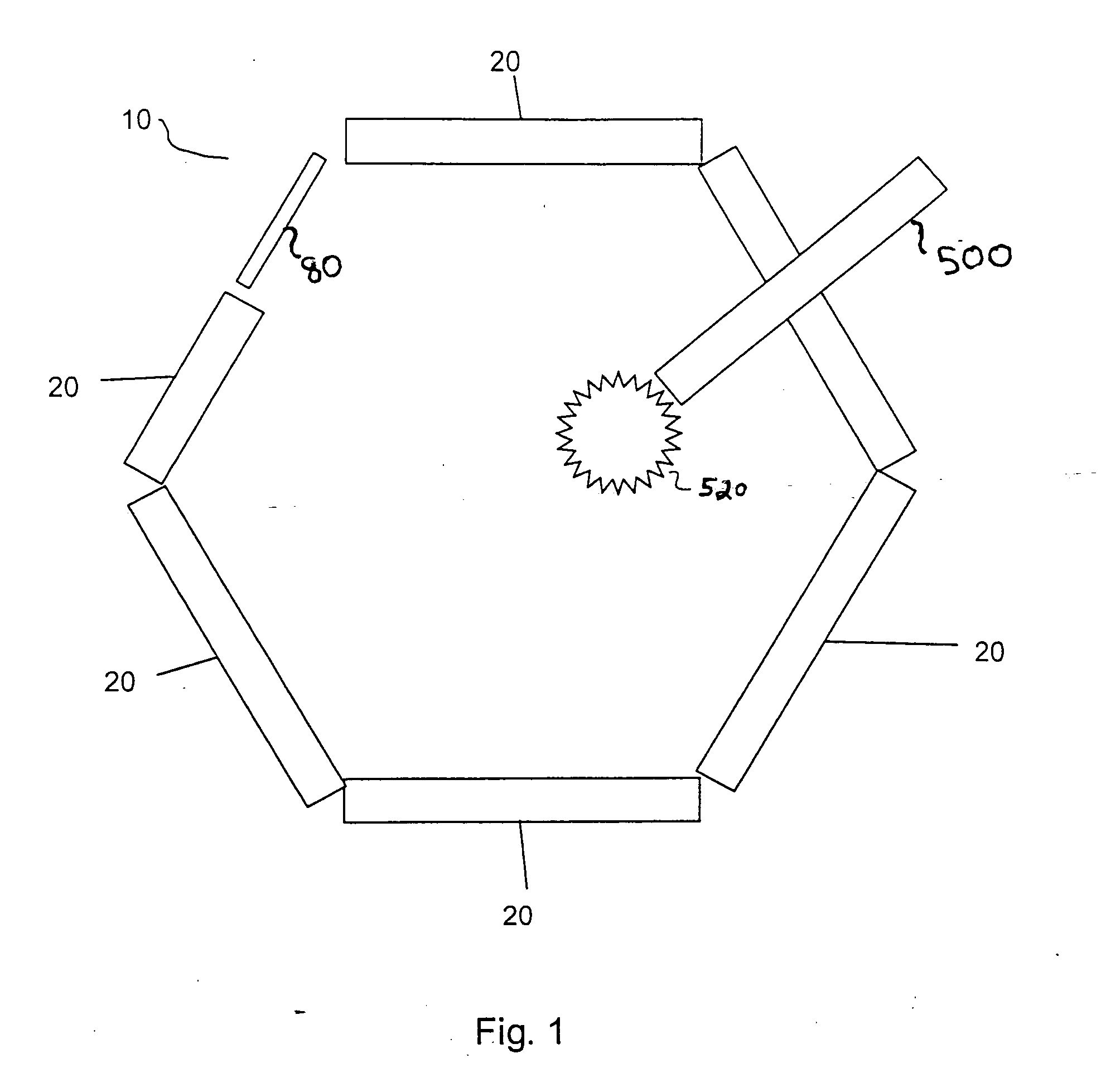
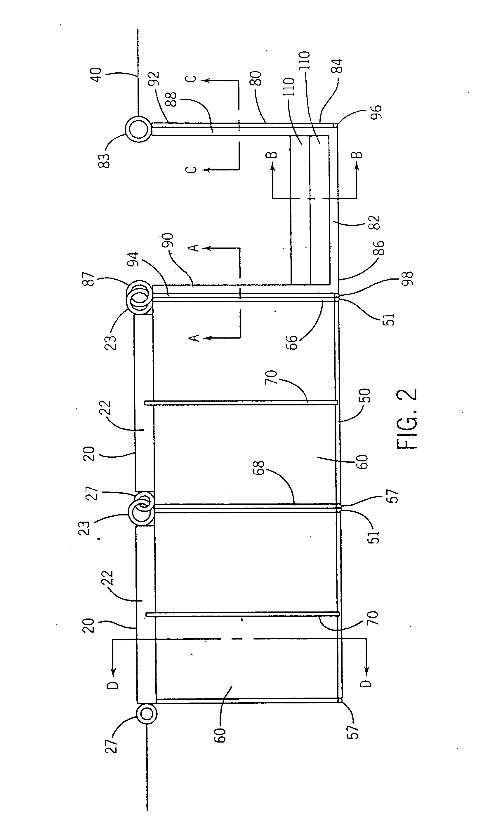
[0048] 3. Erect a sediment-containment structure in the manner described below.

[0049] 4. Introduce sediment into the substantially closed shape formed by the sediment-containment structure.

Additionally, board or other blocking means can be added to a wasteweir segment as the height of sediment buildup increases.

[0050] ...


PUM


Abstract

An article of manufacture produced by a process comprising the steps of: erecting a sediment-containment structure comprising a plurality of floating boom segments; and introducing sediment into the shape formed by the sediment-containment structure. A system for building up sediment in a water-covered area comprises: a plurality of floating boom segments connected in an essentially closed shape; a sediment source depositing sediment inside the area substantially enclosed by the essentially closed shape formed by the boom segments; and a wasteweir segment disposed so as to close the essentially closed shape formed by the floating boom segments. The wasteweir segment has two posts and a removable barrier element. A method for building up land in a water-covered or water-surrounded area comprises the steps of: erecting a sediment-containment structure comprising a plurality of floating boom; and introducing sediment into the shape formed by the sediment-containment structure.

Description

CROSS-REFERENCE TO RELATED APPLICATIONS [0001] This application is a continuation-in-part of applicant's U.S. patent application Ser. No. 10 / 695,640, which is a continuation-in-part of applicant's U.S. patent application Ser. No. 10 / 349,599, filed Jan. 23, 2003, now U.S. Pat. No. 6,827,525 B2. The disclosures of U.S. patent application Ser. No. 10 / 695,640, U.S. patent application Ser. No. 10 / 349,599, and U.S. Pat. No. 6,827,525 B2 are incorporated herein by reference.STATEMENT REGARDING FEDERALLY SPONSORED RESEARCH OR DEVELOPMENT: [0002] Not applicable. REFERENCE TO SEQUENCE LISTING, TABLE, OR COMPUTER PROGRAM LISTING SUBMITTED ON COMPACT DISK: [0003] Not applicable. BACKGROUND OF THE INVENTION [0004] (1) Field of the Invention [0005] The invention relates to the field of building up land in water-covered or water-surrounded areas and more specifically to the field of restoring land in coastal wetlands where erosion has caused land loss. This invention also relates to the field of b...

Claims


Application Information

Patent Timeline
Patent Type & Authority Applications(United States)
IPC IPC(8): B09C1/00E02B3/18
CPCE02B3/18B09B1/00
Inventor CHERAMIE, RICKEY
Owner SAMSUNG ELECTRONICS CO LTD
Why Eureka
Try Eureka