Configuration for nuclear magnetic resonance imaging (MRI) with an MRI phantom

a technology phantom, which is applied in the field of nuclear magnetic resonance imaging (mri) configuration to achieve the effect of improving the efficiency of phantom measurements and the number of measurements

Active Publication Date: 2007-03-29
BRUKER BIOSPIN MRI
View PDF10 Cites 5 Cited by
  • Summary
  • Abstract
  • Description
  • Claims
  • Application Information

AI Technical Summary

Benefits of technology

[0014] An MRI phantom of this type only comprises a small dead volume (partial volume containing the gas bubble) such that, despite the compact design, recordings can be performed in the largest part of the chamber, i.e. the main chamber, without disturbances. The limitation of the partial chamber also largely suppresses disturbances in the main chamber caused by vibrations due to the gas bubble located in the partial chamber.
[0020] With particular preference, the partial chamber is disposed on an axial end of the housing. The MRI phantom can therefore be disposed in a simple fashion, such that the partial chamber is outside of the measuring plane.
[0027] The housing of the MRI phantom is preferably made from transparent plastic material, in particular, from polycarbonates or polymethyl methacrylate (PMMA). The position of the gas bubble can thereby be controlled in a simple fashion.
[0032] The inventive method obviates refilling of MRI phantoms to avoid gas bubbles within the liquid in the MRI phantom housing. The number of measurements which cannot be utilized due to gas bubble artefacts is reduced and the efficiency of the phantom measurements is improved.
[0033] In an advantageous variant of the inventive method, the imaging partial volume has the shape of an upright disc. The advantages of the invention can thereby be utilized in a particularly advantageous fashion, since gas bubbles cause serious problems when such partial volumes are imaged using conventional methods.

Problems solved by technology

Moreover, the switching of gradients during MRI recording can cause vibrations of the gas bubble and thereby pressure waves within the liquid in the MRI phantom which produces signal variations within the image plane and thereby artefacts.

Method used


Image

  • Configuration for nuclear magnetic resonance imaging (MRI) with an MRI phantom
  • Configuration for nuclear magnetic resonance imaging (MRI) with an MRI phantom
  • Configuration for nuclear magnetic resonance imaging (MRI) with an MRI phantom

Examples


Embodiment Construction

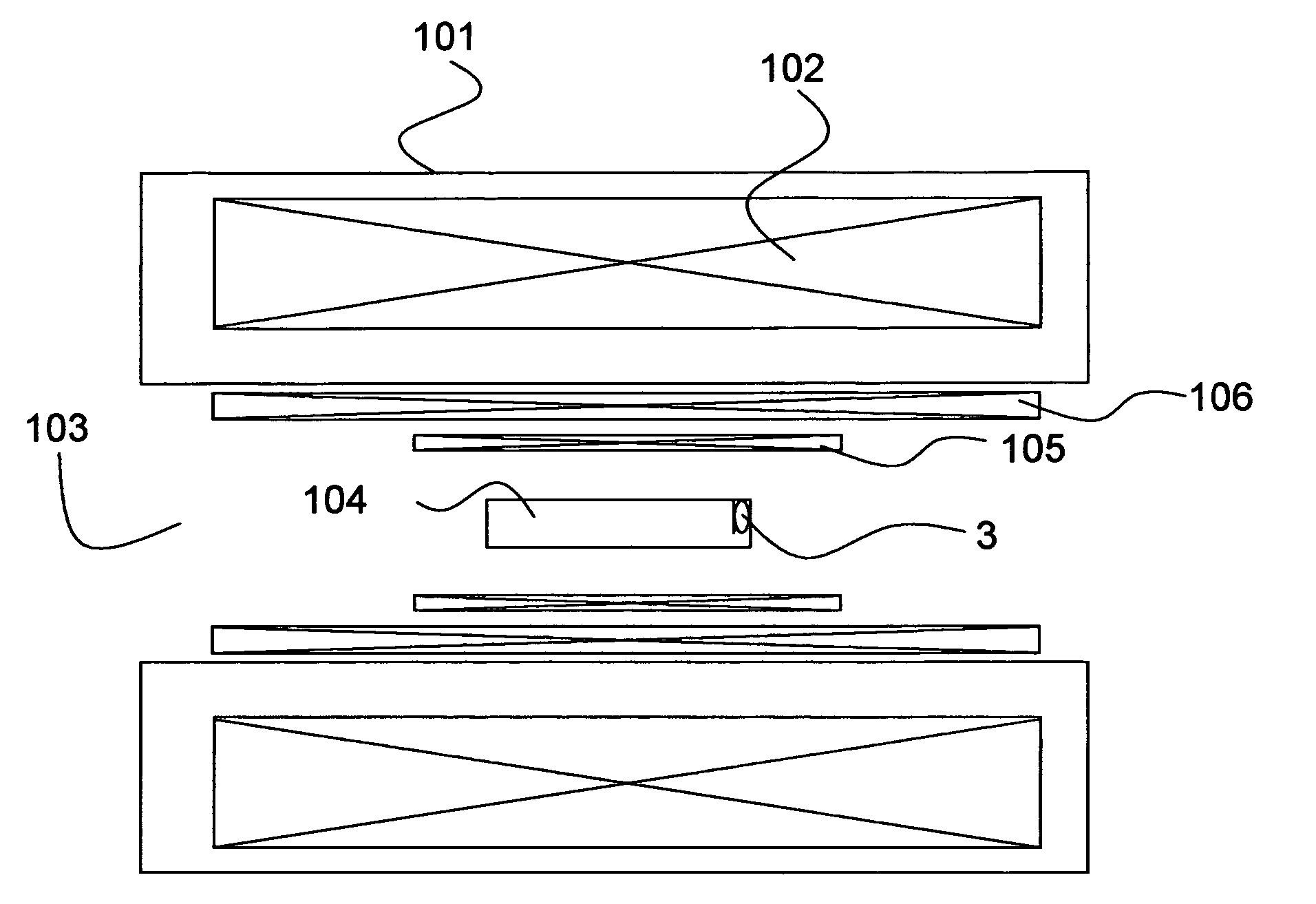
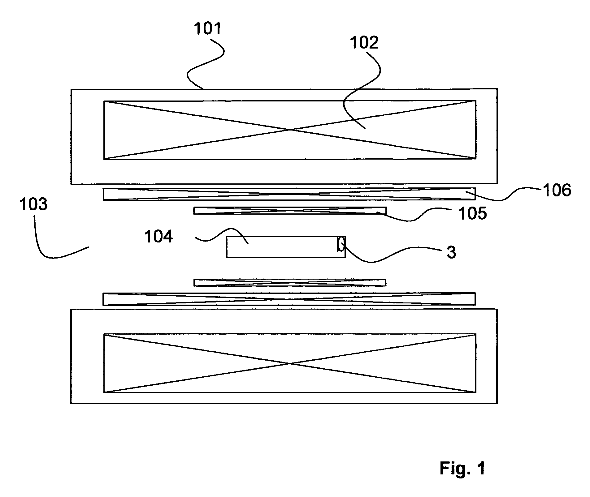
[0042]FIG. 1 shows a sectional view of an inventive MRI configuration with a magnet coil system 102 disposed in a cryostat 101. The inventive MRI configuration moreover comprises a radio frequency (RF) system 105 and a gradient system 106. An MRI phantom 104 is disposed in a volume under investigation located in a room temperature bore 103, which is filled with a liquid and in which a gas bubble 3 forms.

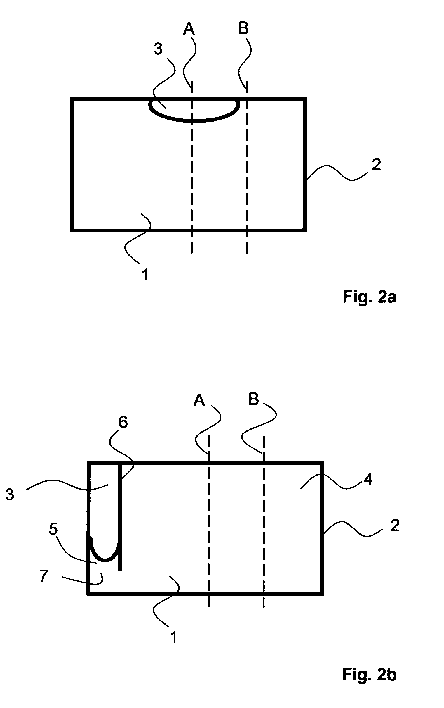
[0043]FIG. 2a shows a cross-section of an MRI phantom according to prior art. The MRI phantom comprises a chamber 1 which is delimited by a housing 2. The chamber 1 is filled with a liquid which is suited for nuclear magnetic resonance and in which a gas bubble 3 has formed. Due to the buoyancy of the gas bubble 3 in the liquid, the gas bubble 3 is located centrally at the upper edge of the chamber 1 in the resting MRI phantom of FIG. 2a. In an MRI recording through a central vertical measuring plane A, there is no signal in the region of the gas bubble 3, such that evaluations such...


PUM

PropertyMeasurementUnit
NMR relaxation time T1aaaaaaaaaa
nuclear magnetic resonance imagingaaaaaaaaaa

Abstract

An MRI configuration comprising a magnet system for generating a homogeneous magnetic field, a radio frequency (RF) system (105) for generating / detecting an RF field B1, and a gradient system (106) for temporarily superposing defined gradient fields on a magnetic field B0, and an MRI phantom (104) positioned in the volume under investigation, wherein the MRI phantom (104) comprises a chamber (1) disposed in a housing (2) and filled with a liquid, in which a gas bubble (3) forms, wherein the liquid contains nuclei which have an NMR relaxation time T1, of between 100 ms and 20 s, is characterized in that the chamber (1) of the MRI phantom (104) comprises a main chamber (4) and a partial chamber (5), wherein the main chamber (4) is delimited from the partial chamber (5) such that the gas bubble (3) can completely enter the partial chamber (5) due to its buoyancy by changing the spatial orientation of the MRI phantom (104) in the gravitation field, and remains in the partial chamber (5) in a measurement orientation of the MRI phantom (104) due to its buoyancy. This eliminates imaging artefacts despite the presence of a gas bubble.

Description

[0001] This application claims Paris Convention priority of DE 10 2005 045 679.0 filed Sep. 24, 2005 the complete disclosure of which is hereby incorporated by reference. BACKGROUND OF THE INVENTION [0002] The invention concerns a nuclear magnetic resonance imaging (MRI) configuration with a magnet system for generating a homogeneous magnetic field B0 in a volume under investigation, a radio frequency (RF) system for generating an RF field B1 in the volume under investigation or for detecting an RF field B1 from the volume under investigation, with a gradient system for temporarily superposing defined gradient fields on the magnetic field B0, and an MRI phantom positioned in the volume under investigation, which aids in determining the homogeneity of the magnetic field B0 and / or the RF field B1 and / or the linearity and / or intensity and / or scaling of the gradient fields in the volume under investigation, wherein the NMR phantom comprises a chamber which is disposed in a housing and f...

Claims


Application Information

Patent Timeline
Patent Type & Authority Applications(United States)
IPC IPC(8): G01V3/00G01N24/00A61B5/05
CPCY10T436/24G01R33/583A61B5/055G01R33/58
Inventor KREIBICH, WOLFGANG
Owner BRUKER BIOSPIN MRI
Why Eureka
Try Eureka