Laser ranging with large-format VCSEL array

a technology of vcsel array and laser ranging, which is applied in the direction of semiconductor lasers, using reradiation, instruments, etc., can solve the problems that system having relatively delicate opto-mechanical parts such as rotating mirrors may not be sufficiently rugged and durable for long-term reliability in an automobile or similar vehicle under typical use conditions, and similar opto-mechanical assemblies may not be sufficiently economical for widespread commercial acceptance, so as to achieve the effect of being especially economical and reliabl

Inactive Publication Date: 2007-03-29
AVAGO TECHNOLOGIED FIBER IP SINGAPORE PTE LTD
View PDF4 Cites 106 Cited by
  • Summary
  • Abstract
  • Description
  • Claims
  • Application Information

AI Technical Summary

Benefits of technology

[0005] In an exemplary embodiment of the invention, the optical elements can comprise microlenses that are either integrally formed with the VCSEL structure or as a separate structure bonded or otherwise attached to the VCSEL structure. This embodiment may be especially economical and reliable, as the lasers and microlenses together form a unitary and solid structure, relatively immune to damage from vibration and other hazards of an automotive environment. By arraying the la

Problems solved by technology

Although the above-described laser ranging system may work well in experimental installations, a system having relatively delicate opto-mechanical parts such as a rotating mirror may not be sufficiently rugged and durable for l

Method used


Image

  • Laser ranging with large-format VCSEL array
  • Laser ranging with large-format VCSEL array
  • Laser ranging with large-format VCSEL array

Examples


Embodiment Construction

[0025] In the following description, like reference numerals indicate like components to enhance the understanding of the invention through the description of the drawings. The drawing figures are not to scale. Also, although specific features, configurations, arrangements and steps are discussed below, it should be understood that such specificity is for illustrative purposes only. A person skilled in the relevant art will recognize that other features, configurations, arrangements and steps are useful without departing from the spirit and scope of the invention.

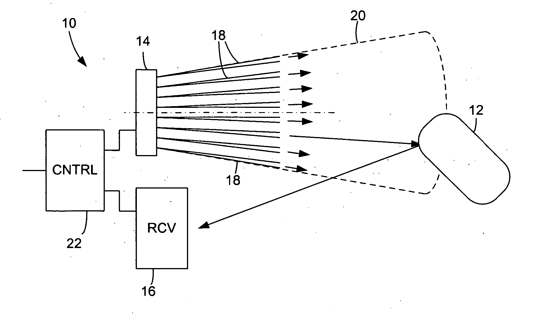
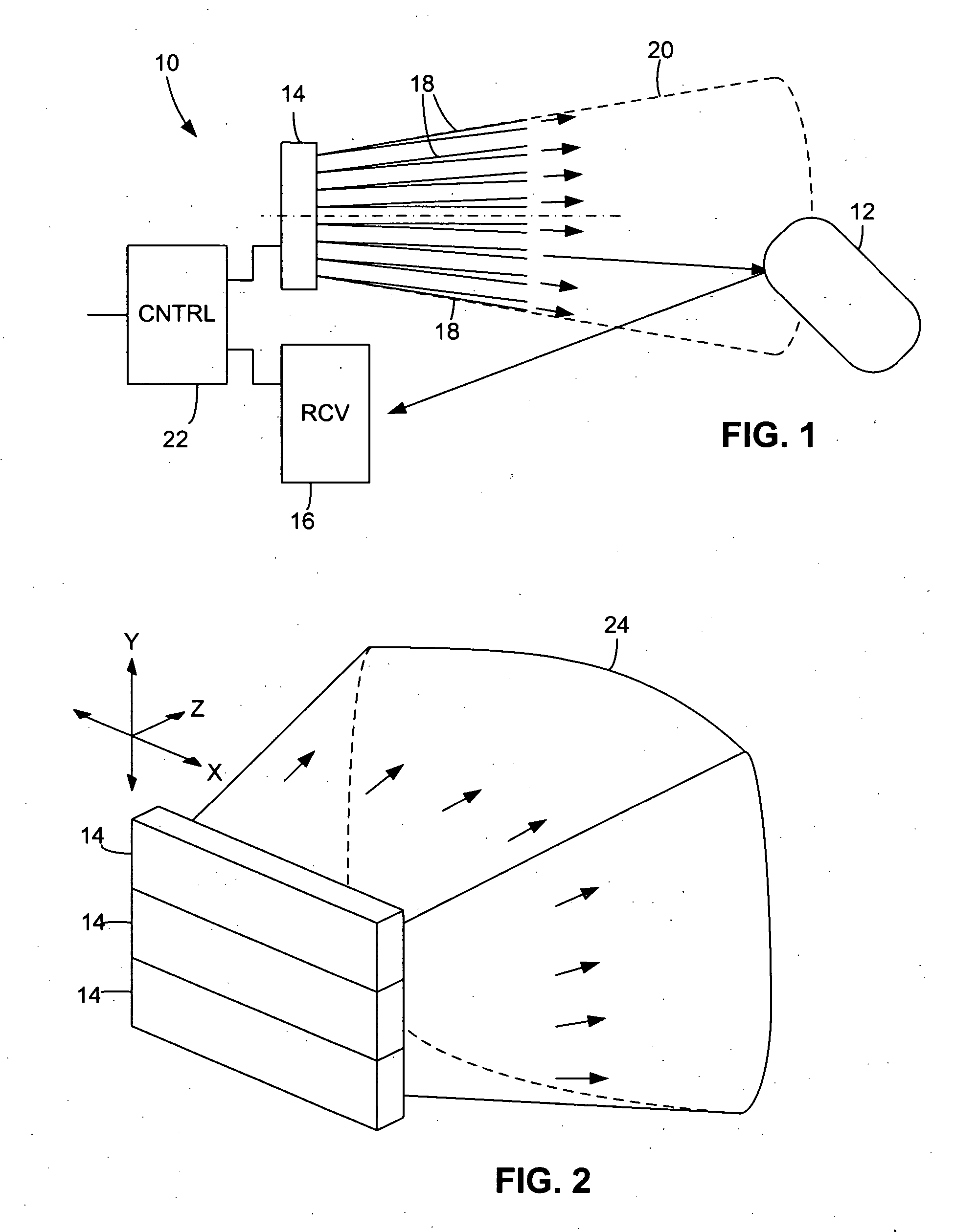
[0026] As illustrated in FIG. 1, a laser ranging apparatus 10 that can detect the distance (range) and location (bearing) of objects 12 includes a vertical-cavity surface-emitting laser (VCSEL)-based emitting structure 14 and a receiving structure 16. Emitting structure 14 emits a number of laser beams 18 that fan out over a region of view 20 of several meters. The beams, which are represented in FIG. 1 in the far-field of...


PUM


Abstract

The present invention relates to laser ranging and detection by sequentially emitting a plurality of beams from a vertical-cavity surface-emitting laser (VCSEL) structure, re-directing the beams through optical elements such that they are fanned out over the region of view, and detecting any beams that may be reflected by objects in the region of view. The range and bearing of such objects can be determined from the beam time-of-flight and beam angle.

Description

BACKGROUND OF THE INVENTION [0001] There has been significant interest in automotive vehicle collision avoidance systems that use LIDAR (Light Detection And Ranging) to detect obstacles. Similar laser-based detection systems have been developed in other fields as well. In a typical example of a LIDAR or laser-based obstacle-detection system for automobiles, a mechanically operated mirror sweeps or scans a laser beam across a region of view. An object in the region of view reflects the beam, which is then detected by an optoelectronic detector. The laser, mirror assembly, and detector are all contained in a unit mounted in the front end of the automobile. By pulsing the laser and timing the difference between emitting a pulse and detecting a reflected pulse, the system can calculate the range to the object. Also, by determining the relative positions of the mirror at the time the pulses were emitted and detected, the system can determine the bearing of the object. Uses for such syste...

Claims


Application Information

Patent Timeline
IPC IPC(8): H01S5/00
CPCG01S7/4814G01S7/484G01S17/42G01S17/87G02B3/0006H01S5/423G02B3/0056G02B5/1885H01S5/005H01S5/18305G02B3/0018
Inventor CHEN, YE
Owner AVAGO TECHNOLOGIED FIBER IP SINGAPORE PTE LTD
Why Eureka
Try Eureka