Switch proxy for providing emergency stand-alone service in remote access systems

a stand-alone service and switch proxy technology, applied in the field of switch proxy, can solve the problems of confounded severity of the problem, subscribers terminated on the remote system still cannot communicate with one another, and no longer have telephone service for subscribers served by the remote terminal

Active Publication Date: 2007-03-29
AZTEK ENG +1
View PDF3 Cites 16 Cited by
  • Summary
  • Abstract
  • Description
  • Claims
  • Application Information

AI Technical Summary

Benefits of technology

[0019] Importantly, the switch proxy's translation database is maintained by a switch proxy management system, this translation database as a minimum maintains correspondence between a telephone subscriber's physical appearance (port address) on the remote terminal and its telephone number. Advantageously, as subscribers are rearranged by the telephone service provider, change orders for several remote terminals may be received

Problems solved by technology

The simplicity of aggregating all of the call control functionality in the host switching system creates a problem in the art.
That is, when the host switching system is unable to communicate with the remote terminal, either through failure of components of the digital trunks or of the switching system itself, subscribers served by the remote terminal no longer have any telephone service.
Even though the connectivity with the greater network is lost and the remote terminal may be otherwise fully functional, the subscribers terminated on this remote system still cannot communicate with one another.
The severity of this problem may be confounded by the fact that these subscribers are frequently served by this technology precisely because they are remote.
These remote settings necessitate the use of local emergency responders and limit other communications options (e.g., cellular telephony).
In urban deployments, the loss of connectivity to an access system may be only a minor inconvenience; nearby neighbors may be served from another system and cellular service will probably be available.
These rural communities could be very isolated from other

Method used


Image

  • Switch proxy for providing emergency stand-alone service in remote access systems
  • Switch proxy for providing emergency stand-alone service in remote access systems
  • Switch proxy for providing emergency stand-alone service in remote access systems

Examples


Embodiment Construction

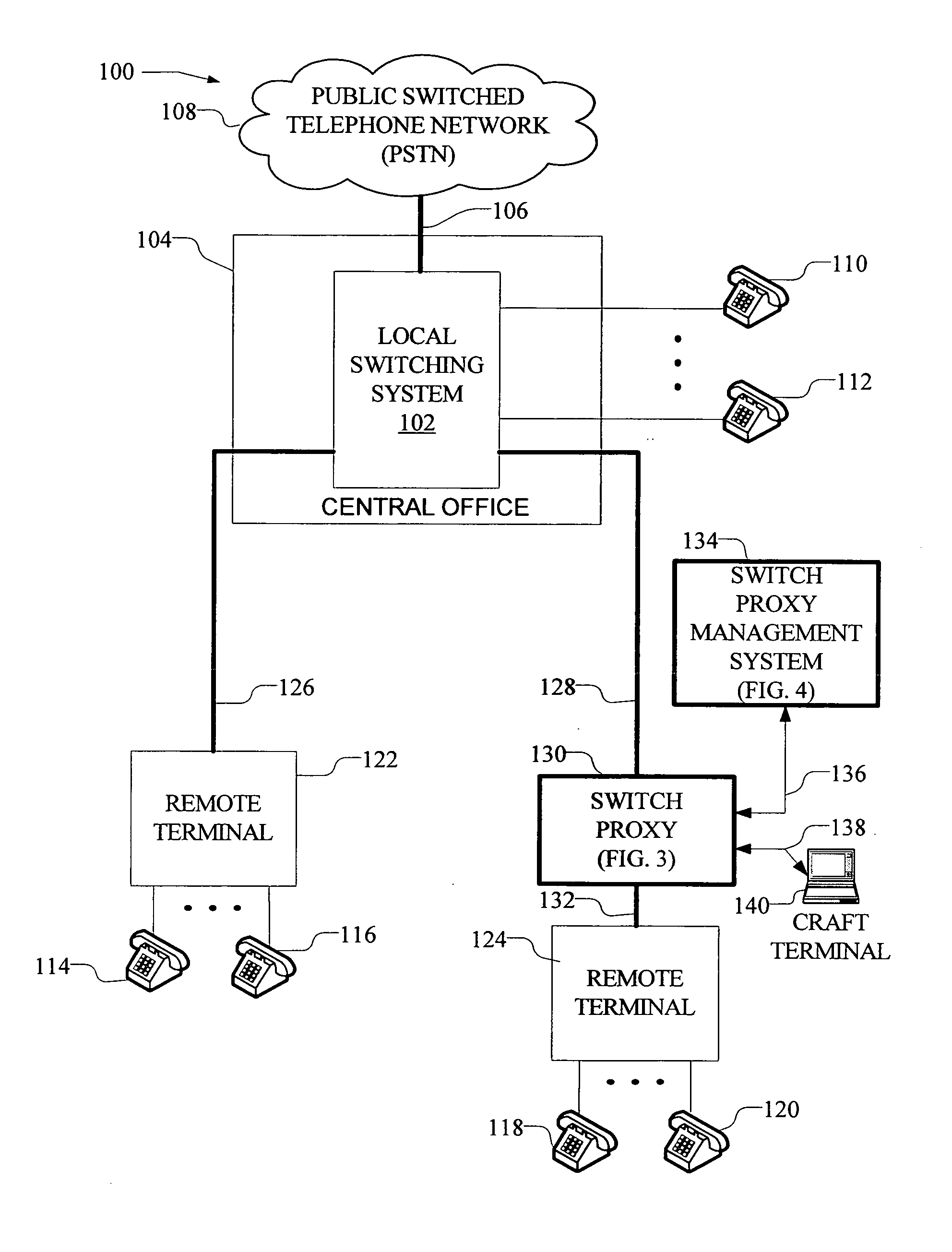
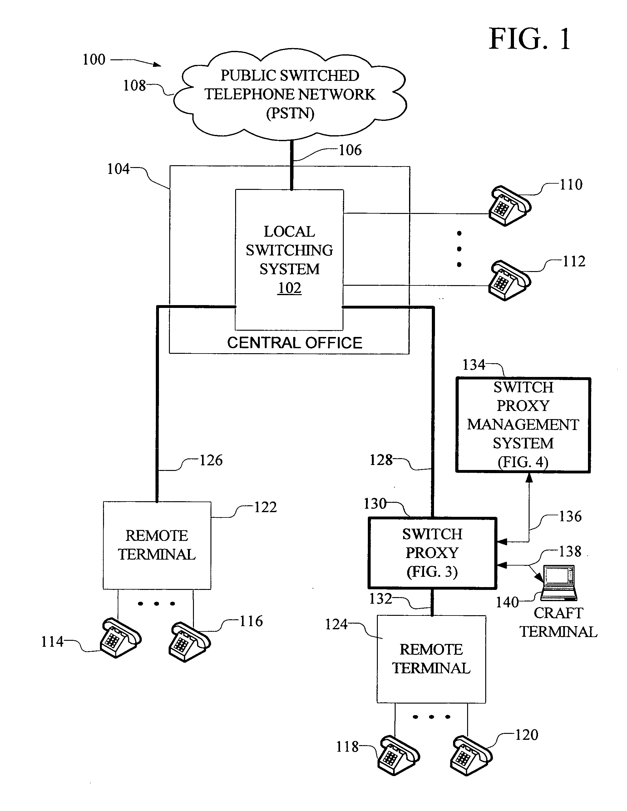
[0029]FIG. 1 is a block diagram of a wireline local telephone network 100 in which an exemplary embodiment of this invention operates. In the wireline local telephone network 100 of FIG. 1, a local switching system 102 (also referred to herein as local switch 102 or switching system 102), typically residing in a central office 104 is connected through trunk group 106 to the public switched telephone network (PSTN) 108 which provides for interconnectivity with subscribers worldwide. This configuration is used herein for convenience and clarity in describing the invention; it is well known in the art that local switching system 102 is part of PSTN 108. A plurality of telephone subscribers 110, 112 may be connected directly to the local switching system through subscriber lines. Additionally, a plurality of subscribers 114, 116, 118, and 120 may be supported from remote terminals 122 and 124 which interconnect to the local switch through trunk groups 126 and 128 respectively. In the pr...


PUM


Abstract

A switch proxy comprising a controller, a translations database and a switching fabric are connected to a trunk group between a remote terminal and its controlling local switching system. The switch proxy monitors control and alarm signals to and from the switching system on the trunk. In the event of loss of control signals from the host switching system, the switch proxy intercepts requests for service, etc. from a calling telephone connected to the remote terminal and performs a look up in the translation database. If the call can be completed without the controlling switching system the call is looped back to the remote terminal. The translation database is maintained by a switch proxy management system that receives change orders from the local exchange carrier. The switch proxy management system forwards relevant changes to the switch proxy's translation database in the field.

Description

RELATED APPLICATION [0001] The present application is a continuation-in-part of U.S. Patent Application Ser. No. 11 / 257,140, entitled “Switch Proxy for Providing Emergency Stand Alone Service in Remote Access Systems,” filed on Oct. 24, 2005. The present application also claims priority to U.S. Provisional Patent Application 60 / 694,146, filed on Jun. 27, 2005.BACKGROUND OF THE INVENTION [0002] This invention relates to access systems as used in wireline telephony and, more specifically, to a switch proxy for use in conjunction with an access system remote terminal to route telephone calls when communications between a remote terminal of an access system and its controlling switching system is lost. [0003] Wireline telephone service providers use access systems to serve telephone subscribers that are not economically or practically served directly from the nearest local switching system. Examples of access systems of this type include subscriber loop carriers and digital loop carrier...

Claims


Application Information

Patent Timeline
IPC IPC(8): H04M11/04
CPCH04M11/04H04M11/007
Inventor ELDER, JOSEPH MARCUSRUETHER, PETER GADE
Owner AZTEK ENG
Why Eureka
Try Eureka