Method and apparatus for judging direction of blur and computer-readable recording medium storing a program therefor

a computer-readable recording medium and program-storing technology, applied in the field of method and apparatus for judging the direction of blur and computer-readable recording medium storing a program therefor, can solve the problems of difficult installation of such hardware in a small imaging device such as a camera phone, camera shake tends to occur due, and the effect of improving processing efficiency

Active Publication Date: 2007-03-29
FUJIFILM CORP +1
View PDF20 Cites 23 Cited by
  • Summary
  • Abstract
  • Description
  • Claims
  • Application Information

AI Technical Summary

Benefits of technology

[0038] In the case where the width of blur is found based on the value or values of the weighting parameter or parameters for the statistical characteristic quantity or quantities representing the direction of blur, the width of blur can be found without image analysis processing such as edge detection, which enables simpler configuration and improvement in processing efficiency.
[0039] Likewise, in the case where the blur in the structure in the input image is corrected by changing the value or values of the weighting parameter or parameters for the statistical characteristic quantity or quantities representing the direction of blur, the blur can be corrected without other image processing such as sharpness correction, which enables simpler configuration and improvement in processing efficiency.

Problems solved by technology

As a result of reduction in size and weight of imaging devices such as digital cameras and camera phones, camera shake tends to occur due to imaging device movement at the time of shuttering.
Therefore, camera shake tends to become conspicuous in photographed images.
However, the method described in U.S. Patent Application Publication No. 20030002746 needs special hardware such as an angular rate sensor, and installation of such hardware in a small imaging device such as a camera phone is difficult.
Furthermore, no method has been disclosed for detecting camera shake based only on a photographed image in the case where no information is available on camera shake detected by such hardware.

Method used


Image

  • Method and apparatus for judging direction of blur and computer-readable recording medium storing a program therefor
  • Method and apparatus for judging direction of blur and computer-readable recording medium storing a program therefor
  • Method and apparatus for judging direction of blur and computer-readable recording medium storing a program therefor

Examples


Embodiment Construction

[0053] Hereinafter, embodiments of the present invention are described with reference to the accompanying drawings.

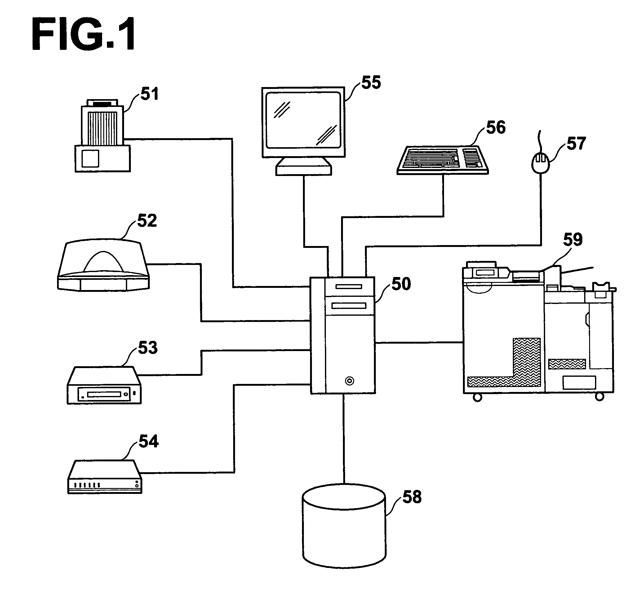
[0054]FIG. 1 shows the hardware configuration of a digital photograph printer in an embodiment of the present invention. As shown in FIG. 1, the digital photograph printer comprises a film scanner 51, a flat head scanner 52, a media drive 53, a network adapter 54, a display 55, a keyboard 56, a mouse 57, a hard disc 58, and a photographic print output machine 59, all of which are connected to an arithmetic and control unit 50.

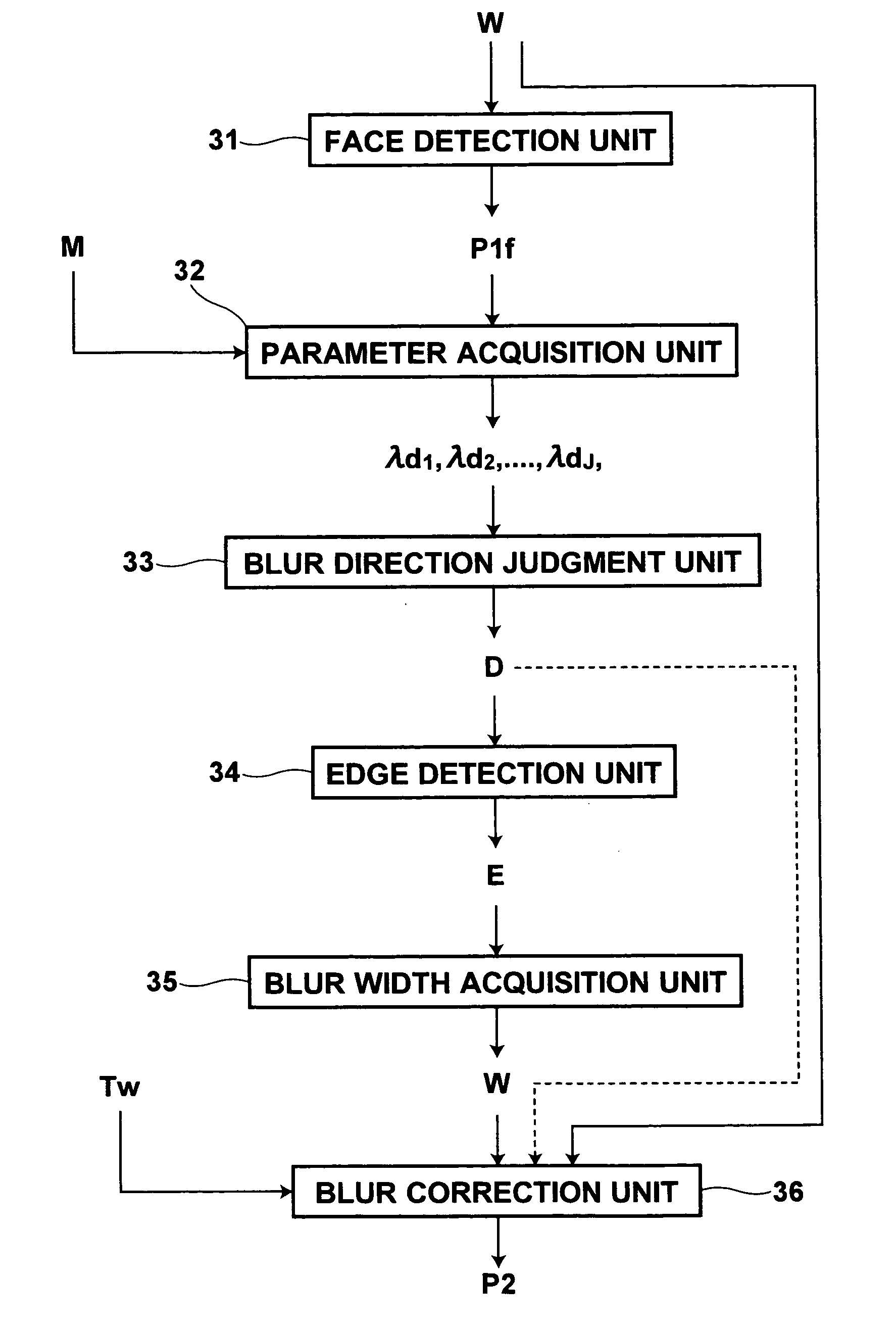
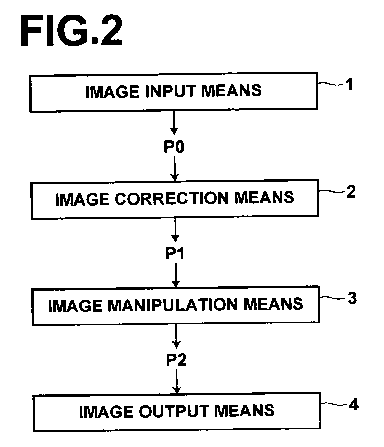
[0055] In cooperation with a CPU, a main storage, and various input / output interfaces, the arithmetic and control unit 50 controls a processing flow regarding an image, such as input, correction, manipulation, and output thereof, by executing a program installed from a recording medium such as a CD-ROM. In addition, the arithmetic and control unit 50 carries out image processing calculation for image correction and manipulation. A blur direction ...


PUM


Abstract

Without use of special hardware such as an angular rate sensor, a direction of blur can be judged with high accuracy. A parameter acquisition unit obtains weighting parameters for principal components representing directions of blur in a predetermined structure in an image by fitting to the structure a mathematical model generated by a method of AAM using a plurality of sample images representing the structure in different conditions of blur. A blur direction judgment unit judges the direction of blur based on the weighting parameters, and a blur width acquisition unit finds a width of blur based on an edge component found by an edge detection unit in the direction perpendicular to the direction of blur. A blur correction unit corrects the blur in the image based on the direction and the width of blur.

Description

BACKGROUND OF THE INVENTION [0001] 1. Field of the Invention [0002] The present invention relates to a method of judging a direction of blur represented in an input image and an apparatus therefor. The present invention also relates to a computer-readable recording medium storing a program that causes a computer to execute the method. [0003] 2. Description of the Related Art [0004] As a result of reduction in size and weight of imaging devices such as digital cameras and camera phones, camera shake tends to occur due to imaging device movement at the time of shuttering. In addition, progress is being made in increase in the number of pixels and in installation of a zooming function as standard equipment. Therefore, camera shake tends to become conspicuous in photographed images. [0005] As a method of detecting such camera shake has been known a method using an angular rate sensor installed in an imaging device (see U.S. Patent Application Publication No. 20030002746). [0006] However...

Claims


Application Information

Patent Timeline
Patent Type & Authority Applications(United States)
IPC IPC(8): G06K9/40
CPCG06T5/003G06T7/0085G06K9/621G06T2207/30201G06K9/00228G06T2207/20201G06T7/13G06V40/161G06V10/7557
Inventor LI, YUANZHONGITO, WATARU
Owner FUJIFILM CORP
Why Eureka
Try Eureka