Transmission antenna diversity

a technology of transmission antenna and diversity, applied in diversity/multi-antenna system, transmission monitoring, site diversity, etc., can solve problems such as unsuitable ep publication solution, poor data transmission quality, and antenna chosen by a mobile station may be misinterpreted at the base station, so as to improve the quality of data transmission

Inactive Publication Date: 2007-03-29
NOKIA TECHNOLOGLES OY
View PDF7 Cites 21 Cited by
  • Summary
  • Abstract
  • Description
  • Claims
  • Application Information

AI Technical Summary

Benefits of technology

[0018] It is an advantage of this kind of transmission antenna diversity that the quality of the data transmission will improve owing to the choice of an individual transmission antenna route. In addition, it is an advantage of the transmission antenna diversity according to the invention that it is possible therein independently to connect simultaneous subscriber connections through some transmission antenna route chosen in accordance with the invention, independently of the transmission antenna routes of other subscriber connections.
[0019] One embodiment of the invention achieves both a reliable message giving the antenna route choice information and a simple identification of the antenna route to be used for the transmission, whereby the receiving unit will always be aware of the transmission antenna route which is to be used for the transmission. Some embodiments of the invention have the advantage that they need less hash codes for spreading the transmission than in known transmission diversity solutions, when every antenna route does not need its own hash code.

Problems solved by technology

The broadband signals of other subscribers represent noise in the receiver beside the desired signal.
Non-idealities of the transmission channel, such as signal reflections, noise and interference caused by other connections, will cause changes in the signal containing the information, so the signal perceived by the receiver is never an exact copy of the signal transmitted by the sender.
In a mobile communications system environment, the reliable transmission is disturbed by signal fading on the radio path.
It is a problem with known transmission antenna diversity methods and with the solution of the EP publication described above that the choice of antenna is centralised jointly for all subscriber connections, whereby all traffic is directed for transmission by way of one antenna.
Thus, the solution of the EP publication is not suitable for setting up several simultaneous subscriber connections by way of different antennas.
It is another problem that the antenna chosen by a mobile station may be misinterpreted at the base station, when the choice notification is based on information of one bit or a few bits in the individual message.
Due to data transmission errors, this information may be erroneous in the reception.
If the base station misinterprets the antenna chosen by the mobile station and then transmits by way of the misinterpreted antenna, the data transmission quality will suffer from the base station to the mobile station, as the mobile station assumes that the transmission comes from the antenna it has chosen.
If the choice of antenna is misinterpreted at the base station, then e.g. the interpretation of power control bits may fail in the downlink direction.
A further problem with the EP publication described above is that channels set up through different antennas are not orthogonal in relation to one another, whereby they will cause interference to each other.

Method used


Image

  • Transmission antenna diversity
  • Transmission antenna diversity
  • Transmission antenna diversity

Examples


first embodiment

[0053] The invention was described above in the case of a connection between one base station BS and one mobile station MS. FIG. 9 shows the invention in a situation, where mobile station MS is simultaneously connected with more than one base station, but the functionality according to the invention is applied to one connection only. In the example shown in FIG. 9, the functionality according to the invention is applied to the connection between mobile station MS and base station BS3, whereby for the connections between mobile station MS and base stations BS1 and BS2 some such transmission antenna route is used, which is chosen by some state-of-the-art method. In the situation shown in FIG. 9, e.g. in a soft handover situation, base station BS3 thus through all its transmission antennas ANT1 and ANT2 transmits a common channel, whose signal has been shaped by a transmission antenna beam specific signal shaping method. Mobile station MS compares the received signals with one another ...

fourth embodiment

[0060] In the invention, the functionality according to the invention can be turned off for the time of a soft handover situation. If the choice of transmission antenna route according to the invention is performed at standard intervals of time, this may be implemented e.g. by a message from mobile station MS to the network in a soft handover message. Mobile station MS may make known in this message, that no antenna route choice message in accordance with the invention will be transmitted for the time being. When the soft handover situation is over, mobile station MS may send to the network a message that the choice of antenna route continues or it may simply send the antenna route choice message to the base station among the data which is to be sent to the base station. If the choice of transmission antenna route is performed at a random moment, the functionality according to the invention can be most easily turned off for the time of a soft handover situation in such a way that mo...

fifth embodiment

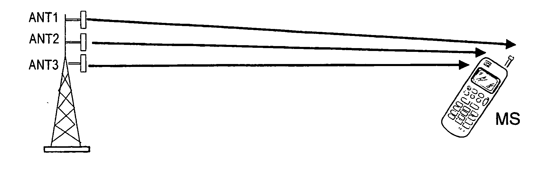
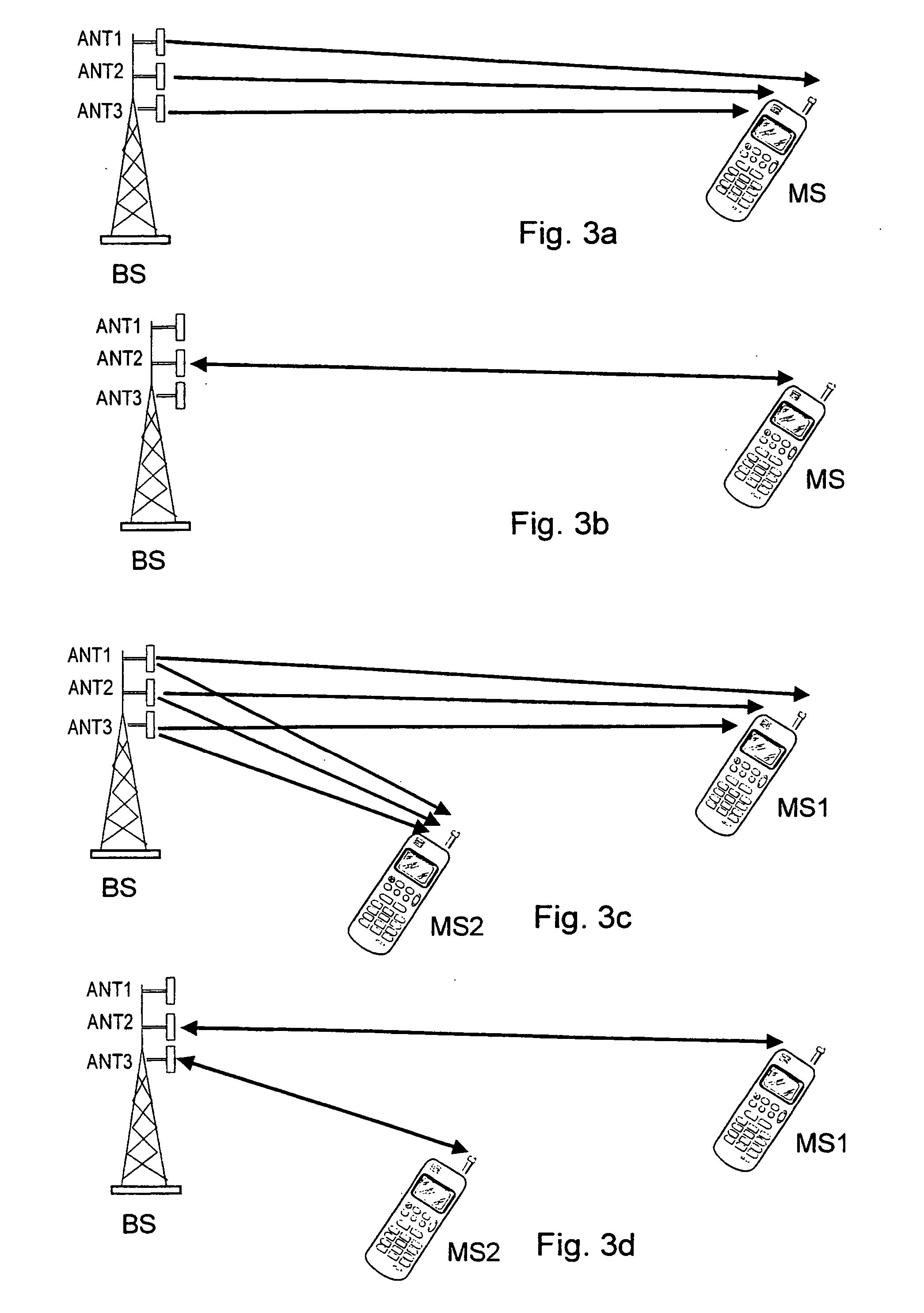
[0061] In the invention, the base station transmits essentially at the same time through its several transmission antenna routes to mobile station MS on the traffic channel an identifier identifying the individual transmission antenna route, e.g. in the case shown in FIG. 3a through transmission antennas ANT1-ANT3. Mobile station MS receives the traffic channel signal of all transmission antenna routes and from these received signals it determines which one is best, e.g. based on the signal level, the SIR (Signal to Interference Ratio) or the distance attenuation. Mobile station MS notifies base station BS of the best transmission antenna route of its choice with the aid of an identifier which it has perceived in the traffic channel signal of the concerned transmission antenna route. With the aid of bit sequences of the identifier it is also possible to improve the comparison of signals of the transmission antenna routes in the receiving unit. Using these it is e.g. possible to calc...


PUM


Abstract

In mobile communications systems transmission antenna diversity is used e.g. to compensate for fading caused to the signal on the radio path. It is known to make the choice of transmission antenna jointly for all subscriber connections, but it is not hereby possible to offer the optimum transmission antenna to simultaneous connections. The present invention aims at a method for implementing transmission antenna diversity on a data transmission connection, which is set up between a transmitting unit (BS), wherein there are several transmission antenna routes (ANT1, ANT2, ANT3), and a receiving unit (MS1, MS2). In the method, a broadcast signal is transmitted through all transmission antenna routes (ANT1, ANT2, ANT3) of the transmitting unit, with the aid of these signals a choice is made in the receiving unit (MS1, MS2) of the optimum transmission antenna route and a message of the choice is transmitted to the transmitting unit (BS), which transmits user data through the transmission antenna route connected for use. According to the invention, the method is characterised in that the broadcast signal of each transmission antenna route is shaped by an individual signal shaping method which is different from the others and a transmission antenna route is connected for use based on the received antenna choice message, individually for each receiving unit.

Description

CROSS-REFERENCE TO RELATED APPLICATIONS [0001] This application is a continuation of U.S. patent application Ser. No. 09 / 660,668, filed Sep. 13, 2000, which is a continuation of International Application No. PCT / FI99 / 00334, filed Apr. 23, 1999, and claims priority from Finnish Patent Application No. 980915 filed on Apr. 24, 1998 and Finnish Patent Application No. 981377 filed on Jun. 12, 1998. The disclosures of the prior applications are hereby incorporated by reference.FIELD OF THE INVENTION [0002] The invention concerns a method and an arrangement for arranging transmission antenna diversity in a mobile communication system. BACKGROUND OF THE INVENTION [0003] In radio systems implemented by CDMA (Code Division Multiple Access), the operation is based on scattered spectrum communication. The transmitted signal is scattered by an individual hash code Wi, e.g. a Walsh code, addressed to the subscriber, whereby the transmission is spread out on a broadband radio channel, which is e.g...

Claims


Application Information

Patent Timeline
Patent Type & Authority Applications(United States)
IPC IPC(8): H04B17/00H04B7/08H04B1/06H04B7/02H04B7/04H04B7/06H04L1/00H04L1/06
CPCH04B7/022H04B7/0408H04L1/06H04L1/0065H04L1/0071H04B7/061
Inventor HOTTINEN, ARIWICHMAN, RISTO
Owner NOKIA TECHNOLOGLES OY
Why Eureka
Try Eureka